Assignment Week #4 – DNA

Concept:

Drawing inspiration from the structure of DNA, the goal behind this project was to visually represent a DNA helix. A DNA helix is composed of two spiral strands, interlinked by rung-like structures, mimicking a twisted ladder. The project also allows interactive elements, enabling users to manipulate the visual representation of the helix. Users can control the radius and segment length of the helix by moving the mouse and can also manipulate the rotation speed using the arrow keys.

Implementation:

Helix:

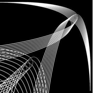
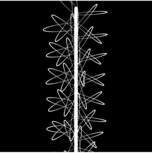
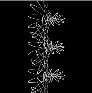
  • Helix: Two helixes are drawn to represent the twisted strands of the DNA helix, each spiral strand having base pairs represented by ellipses. Lines connecting these ellipses create an aesthetic and illustrative representation of a DNA helix.

User interactivity:

  • Radius and Segment Length Control: By pressing and holding the mouse button, users can change the helix’s radius and segment length, creating varied visual effects. The X-coordinate of the mouse controls the radius, and the Y-coordinate controls the segment length.
  • Rotation Speed Control: The UP_ARROW key increases the rotation speed of the helix, while the DOWN_ARROW key decreases it, allowing users to explore the helix structure in a dynamic manner.

Sketch:

Code:

Here is a snippet of the main interactivity features implemented in the code:

for (let i = 0; i < numSegments; i++) {
    let angle1 = i * angleIncrement + angle;
    let angle2 = angle1 + PI; 
    let x1 = helixRadius * sin(angle1);
    let y1 = i * segmentLength;
    let x2 = helixRadius * sin(angle2);
    let y2 = (i + 1) * segmentLength;
    
    ellipse(x1, y1, 10, 10);
    ellipse(x2, y2, 10, 10);
    line(x1, y1, x2, y2);
}
  • It calculates two angles, angle1 and angle2, for each segment, ensuring a 180-degree phase shift between them to depict opposite points in the helix.
  • For each angle, it computes the x and y coordinates (x1, y1, x2, y2) to position the base pairs and draw the segment of the helix.
  • It uses these coordinates to draw two ellipses representing base pairs and a line between them, simulating the structure of DNA.

Challenges:

  • Interactivity Integration: Seamlessly incorporating user controls while maintaining the visual integrity of the helix structure presented a challenge. The controls needed to be intuitive and responsive, allowing users to explore the structure dynamically.
  • Visual Representation: Achieving a visually appealing and accurate representation of a DNA helix, considering the spiral strands and interconnecting lines, required meticulous calculations and adjustments.

Future Improvements:

  • Additional More User Controls: Implement more user controls, like sliders or input fields, enabling users to modify parameters such as color schemes, the density of base pairs, or introducing distortions to the helix structure.
  • Visual Aesthetics Enhancements: Infuse more aesthetic elements like dynamic colors, shadows, and reflections, elevating the visual appeal and depth of the representation.

Assignment #4: The Flamenco Dancer by Abdelrahman Mallasi

Concept

Flamenco is a rhythmic dance form with origins to the Andalusian region of Spain in the late 18th century. It holds influences from Romani, Castilian, and Moors and is characterized by hand claps, intricate footwork, and vibrant guitar playing. Click here to learn more about Flamenco. In this project, I intended to capture the essence and fluidity of Flamenco, particularly the movement of a dancer’s skirt during a performance. The pendulums in the simulation mimic the flow and rhythm of a Flamenco dancer’s skirt. The Flamenco Dancer is inspired by Memo Atken’s use of simple harmonic motion, expanding geometric shapes, and organic motion.

Highlight of Code

pendulums[i] = new Pendulum(x, y, 100 + i * 5, 0.03 * (i + 1));

This piece of code is under the setup function after the for loop to initialize the pendulum objects. It creates a new Pendulum object using the previously calculated x and y as the origin. The arm length of the pendulum is 100 + i * 5. This means the first pendulum has an arm length of 100 pixels, the second 105 pixels, the third 110 pixels, and so on. This creates a visually appealing cascading effect. The frequency of the pendulum is 0.03 * (i + 1). It ensures that each subsequent pendulum oscillates slightly faster than the previous.

this.angularAcceleration = (-0.1 / this.armLength) * (gravity * sin(this.angle));

This code is under the update function of the Pendulum Class. It calculates the pendulum’s angular acceleration based on its displacement from the vertical and the force of gravity. The term (-0.1 / this.armLength) acts as a scaling factor. The -0.1 is an arbitrary constant to make the motion look visually appealing in the simulation, and dividing it by the armLength ensures that pendulums with longer arms have less angular acceleration compared to those with shorter arms. The product (gravity * sin(this.angle)) calculates the force trying to return the pendulum to its equilibrium position. When the pendulum is vertically aligned (at rest), the sine of its angle is 0, meaning there’s no restoring force. When the pendulum is displaced, the sine value changes, and the restoring force comes into play.

Embedded sketch

Link to Sketch

Reflections

  • The breathing quality of the circles give the bobs a visual 3d rotational  movement in and out of the screen rather than just a side-to-side motion
  • The (royalty-free) flamenco music added provided such a nice touch to the final project
  • It was difficult and time-consuming to deal with all the equations and manipulate the values of constants to produce a visually appealing sketch
  • In the real world, simple harmonic motion eventually comes to a halt as it loses energy throughout the motion. In this sketch, I didn’t know how to implement that. In a way, I’m happy that I didn’t – the continuous motion of the bobs is aesthetically satisfying

Coding Assignment “Geometric Flower” – Week 3

Concept and Approach:

For this assignment my intention was to have the movers draw some sort of rose or flower through their attraction to the attractors. I began with the aim of drawing a rose like the one below.

I stumbled upon a code of a sketch that I though I could use as inspiration, however I realized while trying to understand its approach that it utilized the Lorenz Attractor mathematical model which was pretty complicated for me to grapple with. With that said, I did manage to tweak parts of the code to achieve the top part of the rose.

<iframe src=”https://editor.p5js.org/dhabialhosani/full/oQNKBKXil”></iframe>

Reference Code: https://editor.p5js.org/igarizio/sketches/_cmEg1gXg

I was eager to continue exploring the model but I was certain that my approach to drawing a simple rose was far more complicated than it should be. From there I decided to our simpler approach of attractors and movers to achieve my desired design. By applying the formulas and following the methods we learnt I found myself achieving random movements around the attractors, similar to those created in class, which made it even more difficult for me to attempt a sketch of a rose using movers and attractors.

This was when I decided to go for a rather geometric flower. I came across Daniel Schiffmen’s video on drawing mathematical rose patterns which helped me create the markings for where my attractors must lie.

Moving on from that step, I followed steps similar to what we had done with the mover and attractors in class, relying on the distance from the attractors to the movers to calculate the force and updating the acceleration accordingly.

To achieve the second part of the assignment, that is, adding other forces to cause turbulence or repulsion, I created an if mouse pressed condition that contains a force vector that attracts the movers away from the geometric rose attractors. It does so randomly based on where the mover is when the mouse is pressed. This ends up distorting the regular shape of the geometric flower. Once the mouse is released though, the geometric flower slowly starts reforming.

<iframe src=”https://editor.p5js.org/dhabialhosani/full/HHZeJfArz” width =360 height=640></iframe>

While simple, this aspect of the code is one that I am proud of because prior to learning how to create a geometric flower like such, I was confused about where exactly I should be placing my attractors to create the intended designs.

//for loop creates attractor points
      for (let i = 0; i < dots; i++) 
        {
          //mapping the value of 'i' to an angle value between 0 to TWO_PI
           let angle = map(i, 0, dots, 0, TWO_PI);
          //calculating the x and y components based on the angles
           x = cos(angle) * d;
           y = sin(angle) * d;
          //creating new attractor vector
           attractor = (createVector(x, y));
        }

As seen above I created a for loop that loops for a total of six times to create six different attractors. I created a variable called angle that maps the value of I which ranges from 0 to 6 to angle values of a full circle from 0 to 2PI. This way I was able to equally spread my attractors around a full circle creating a flower-like shape. I then just used the trigonometric functions to extract the x and y coordinates of the attractors to be able to then create a vector for the each attractor based on the calculated coordinates.

The repulsion aspect of my code is also one that I am happy with. When I first attempted to tackle the turbulence element of the assignment I was determined to add another attractor somewhere around the canvas having it alter the shape of my geometric flower without completely ruining it. This was difficult to achieve as adding one attractor on a corner did not alter the shape like I imagined it would, and adding multiple around the canvas distorted the flower completely. Following Daniel Schiffmen’s video on attraction on repulsion forces I was able to create a force of repulsion that was only activated if the mouse was pressed.

// repulsion mode if mouse is pressed
      else if (mouseIsPressed) 
      {
        // Calculating repulsion force based on distance. F=(G(m1m2)/||r^2||)
        let forceMagnitude = -5 / (d * d); 
        // Calculating force vector away from the attractor
        forceDirection = p5.Vector.sub(this.position, this.attractor.position);
        forceDirection.normalize();
        forceDirection.mult(forceMagnitude);
        // Adding the force to the repel vactor
        this.repelAttractor.add(forceDirection);
        // Adding the repel vector to the mover's acceleration
        this.acceleration.add(this.repelAttractor);
      }
    }


First I calculated the a magnitude for the force based on the distance between the mover and attractor. In place of the gravity and masses  I added a constant negative number to achieve the repulsion effect. I then calculated the force vector’s direction away from the attractor, got its normal value, multiplied it with the magnitude to achieve a new value which I used as the magnitude for the repulsion force. I then added this force the acceleration which led to the desired repulsion effect.

Reflection and Ideas:

I am not sure how I would further improve on this sketch however I would really like to continue exploring my initial approach with the rose and see how far I could go with that. I am still unsure if it’s possible to create that design using just attractors and movers, but perhaps it is, especially if other methods were introduced.

Code for Reference: 

https://editor.p5js.org/dhabialhosani/sketches/HHZeJfArz

Coding Assignment 3 – Gravity

Concept:

This week’s sketch is a simulation that explores the fundamental force of gravity allowing users to observe how objects interact with each other in response to gravitational attraction and repulsion. It involves two types of entities: movers and attractors, and relies on acceleration, velocity, g-force and mass to move them.

Inspiration:

It is inspired by how gravitational power influences the motion and behavior of celestial bodies.

Code: https://editor.p5js.org/bdr/sketches/rtPleK4cp

Code Walkthrough:
Initialization and Setup:

At first, two arrays are defined ‘movers’ and ‘attractors’ to store instances of the Mover class. The setup function creates a canvas and initializes the simulation with one attractor at the center and four randomly positioned movers with random velocities. Each mover is given a random mass.

Mover Class:

The Mover class represents the moving objects in the simulation. Each mover has a position, velocity, acceleration, and mass which determines the strength of its gravitational attraction. The class includes methods for applying forces, attracting other objects, updating their position and velocity, and displaying itself on the canvas.

AddAttractor():

Users can add attractors to the simulation by double-clicking anywhere on the canvas.

Draw():

The draw function is the core of the simulation. It continuously updates and displays the state of the movers and attractors.
Translate(): It translates the coordinate system to the center of the canvas, making calculations and rendering centered around this point.
Mover-mover interaction: It iterates through each pair of movers to calculate gravitational forces between them. this creates a network of interconnected motions among the movers. Connecting lines are drawn between the movers to visualize these interactions.

Challenges:

One of the challenges I have faced is balancing the strength of gravitational forces to ensure that the simulation is visually appealing and not too chaotic. It took some experimentation and trial and error before finding the right values.

Improvements:

Collision detection: Implement collision detection and response for the movers when they come into close proximity to each other or with the canvas boundaries.

Trail effects: Add trail effects to the movers to visualize their path over time.

Gravitational bodies: Instead of circles, represent movers and attractors as more complex shapes or even images for a more realistic and visually appealing representation.

Assignment #3: Binary Stars System by Abdelrahman Mallasi

Concept

The concept of this project is inspired by Binary Stars. Binary stars are a system of two stars in which one star revolves around the other or both revolve around a common center. The two mover objects in this simulation represent these binary stars that rotate around their center of mass. Upon running the program, users will observe two colorful, glowing mover objects (representing stars) moving around the canvas. These objects are attracted towards an invisible center (or the center of mass) and will continuously orbit around it. I’ve also added a drag force to see how it would affect the orbital movement. The color variations provide a visual representation of the vibrant nature of stars. For more information behind my inspiration, click here.

Highlight of Code

attract(mover) {
    let force = p5.Vector.sub(this.pos, mover.pos);
    let distanceSq = constrain(force.magSq(), 100, 1000);
    let G = 4;  // Gravitational constant for this simulation

// formula
    let strength = G * (this.mass * mover.mass) / distanceSq; 
    force.setMag(strength);
    mover.applyForce(force);
  }
}

The above code is the function of gravitational attraction under the Attractor class. I’m proud of it because it took a lot of experimentation to settle on the values of G and  the constrains for the distanceSq to provide the smoothest visuals.

Embedded Sketch

Link to Sketch

Reflections:

  • Over a longer period, the movers behave unpredictably. They might suddenly accelerate and shoot off into the distance at high speeds or keep spinning ver close to the attractor.
  • I set the drag coefficient to be the small value of 0.05. Larger values disturbed the orbital trajectories too much.
  • I spent a large amount of time manipulating parameters such as the gravitational strength, distanceSq constraints, drag coefficient and such to provide a smooth visual. All these parameters got quite confusing and I arbitrarily changed the values until the program ran smoothly, rather than intentionally inputting specific values.
  • Potential improvement: allowing users to interact by placing attractors or adjusting the properties of the stars.

Week #3 Coding Assignment – Movers & Attractors

https://editor.p5js.org/oae233/sketches/PY1m1F8nQ

Concept / Idea

Originally, I wanted to use invisible attractors with a minimum distance between the attractor & the movers to create the shape of a human skeleton. I would then have this object as a class and have different skeletons attract and repel each other at various points. After I implemented the minimum distance function, I realised that I quite liked the effect it creates with movers, especially when connected to some user input, like the mouse position, it felt like catching the movers in a net and then you’re able to fling them back into an orbit. The lines drawn from the movers to the attractor and the trail effect add interesting visual details.

Functions

So I only added two functions from the ones that were in the original example.

distCheck():

 this function continuously checks if the ditsance between a mover and the attractor is less than that movers minimum distance (defined as distLimit), and if it is, it sets the velocity and acceleration of that mover to 0, causing it to stop

wind():

 this function calls the applyForce function to apply wind with a random direction & magnitude (between certain specified values) only when the mouse is pressed. The purpose of this function is to “shake things up a bit” when the user wants to. Because of the randomness of the wind, the movers stuck to the attractor break free while going at different directions, which makes them more likely to go into interesting orbits instead of just uniformly moving away from the attractor. Other movers lose thier orbit and stick to the attractor instead.

Some code I want to highlight:

I thought I’d highlight the two functions I mentioned above just to show how they would work.

 // "that" , opposed to this, is the attractor, it is passed through to this function in the sketch.js file draw() function 
  distCheck(that) {
    let dist = p5.Vector.dist(this.pos, that.pos);
    if ( dist < this.distLimit){
      this.vel.set(0);
      this.acc.set(0);     
        }  
  }

  wind(){
    if (mouseIsPressed){
    let windy = createVector(random(-10,20),random(-10,5));
    this.applyForce(windy);
    }
  }
}


Future work:

I think it would be really interesting to implement my initial idea and create a skeleton using attractors with distance limits between them and their movers and watch how such a structure might react under different forces acting upon it. I also think more could be done in this example to make it look more visually developed or complex, maybe making the shapes of the movers more dynamic instead of a static circle.

week 2 post

http://<iframe src=”https://editor.p5js.org/xw2399/full/ALOjEcYW-I”></iframe>


I’ve chosen to simulate the flight pattern of a bird. Birds exhibit complex and graceful flight behaviors in nature, and I want to create a simplified simulation that captures some of these characteristics. I’ll focus on controlling the bird’s motion solely by manipulating acceleration, mimicking the bird’s ability to adjust its flight path. In this code, I’ve calculated the acceleration of birds.

week 3 post

http://<iframe src=”https://editor.p5js.org/xw2399/full/IYbVDjIoY”></iframe>

Concept: I  create a visual pattern where multiple objects (movers) move around invisible attractors. These attractors will exert forces on the movers, and I also incorporate additional forces to add turbulence and repulsion, creating an interesting and dynamic design.

References and Inspiration: I’ll draw inspiration from generative art and particle simulations.

Variable and Function Naming: embedded in notations

Reflection and Future Improvements:adding arrows and more shape

Assignment 3 – Attractors and Movers

https://editor.p5js.org/ap6178/sketches/TCSSRFgfS

In this assignment, I wanted to experiment with mostly three kinds of phenomenons: gravitational attraction, turbulence and repulsion. To perform these experiments, I decided on auto-generating movers one at a time until it reaches a maximum threshold (then repeating this step), and placing a few attractors in place.

These attractors have a certain maximum displacement that they can move around with. This is to imitate how attractors in the universe also move by themselves. Movers are attracted to these attractors in place, which change the positions of each mover. But it is also important to remember that there is, in fact, a competition between these attractors. Movers move towards the one that can attract with more force.

When movers are near to each other, they are joined through a line. This resembles a communication channel between two movers in the universe. When they are very near to the attractors, they are sucked in.

This imitation of phenomenons creates a unique generative pattern as seen in the sketch.

Here are a few snippets that I’m particularly happy with:

Attractor.attract()

// gravitational attraction force to a mover
attract(mover) {
  let force = p5.Vector.sub(this.position, mover.position);

  let distance = force.mag();
  distance = constrain(distance, 5, 25); // constrain the distance

  let strength = 50 / (distance * distance); // attraction strength based on distance
  
  force.setMag(strength);
  mover.applyForce(force);
}

Turbulence and Repulsion

// apply forces to movers and display them
for (let mover of movers) {
  for (let attractor of attractors) {
    attractor.attract(mover);
  }
  
  // turbulence and repulsion forces
  let turbulence = createVector(random(-0.1, 0.1), random(-0.1, 0.1));
  mover.applyForce(turbulence);
  
  for (let otherMover of movers) {
    if (mover !== otherMover) {
      let repulsion = p5.Vector.sub(mover.position, otherMover.position);
      let distance = repulsion.mag();
      distance = constrain(distance, 5, 25);
      repulsion.setMag(-1 / (distance * distance));
      mover.applyForce(repulsion);
    }
  }
  
  mover.update();
  mover.display();
}

Future Improvements

I would love to add the drag force to imitate the asteroid belt. More like how certain things may hinder the movements in the universe.

Xiaozao Coding Assignment #3

Concept:

In this assignment, I wanted to generate some minimalist patterns using the interaction force between the attractor and multiple movers. I wanted to keep the visual style simple and reduce the user interaction to focus more on the final patterns that the movement of the objects will be able to create. The parameters that I’ve tried adjusting include the gravitational constant G, the mass of the attractor and the mover, the starting position and velocity of the objects, and the way of calculating the force between the attractor and the movers.

Codes:

I tried to write several p5js sketches that share the same classes and parameters but are slightly different in force functions and the logic behind them.

01

The first one places a line or grid of movers that have no initial velocity. However, the attractor has been set with a constant speed to keep it moving in a straight line, so that it can lead the direction of the movers to a certain extent, based on its own mass, moving speed, and distance from the movers. I created several versions.

02

In the second set of sketches, I changed the movement of the attractor to a circular pattern and placed the movers in a circle to see what would happen. And I discovered something interesting.

When the attractor is moving rather slowly (move by an angle of frameRate/500 every frame), we can see that it places a strong force to the moving direction of the movers. It’s like macaroni.

If we increase the moving rate of the attractor (frameRate/100), we can see that the movers are not heading in the same direction. It’s because the attractor has already changed its position before it puts enough force to the mover to move towards a certain direction.

When the attractor is moving very fast (frameRate/1), you can actually find that its directional impact on the movers is more even. In other words, it’s moving like a centrifugal machine and due to its more rapid change of position, its force on the movers in every direction is evenly distributed. When it is moving extremely fast, we can actually say that it puts no force on the movers at all. This makes me rethink of how the impact of force can change with a change in time scale!

03

In the last experiment, I attempted to create a combination of the gravitational acceleration and the vector acceleration. So what’s the difference between the two?

The gravitational acceleration is calculated through Newton’s second law, which is a rather complicated formula. However, vector acceleration is simply applying the subtraction of the position of the attractor and the position of the mover as a force. I discovered this because I was trying to create a flower-like pattern with the gravitational force but I could never succeed. Later I found out that we can only achieve this through applying the vector force.

Here is the comparison of these two kind of forces. In these two sketches, only the force calculation formula has been changed. (basically one line of code)

Vector force:

Gravitational force:

And then I wrote both of the functions and applied the two forces to the same mover. This is what I got. Look at the movement and you can find there’s a twist each time when the mover is near the attractor. It’s done by the gravitational force.

Then I tried to make the attractor move and also adjusted some parameters. And I got these patterns:

Future direction:

I think the next step can be manipulating more movers instead of a single mover. I can also make more interactive sketches. It’s also a good idea to add a fraction or a force that will push away the mover when it’s too close to the attractor.