
Inspiration:
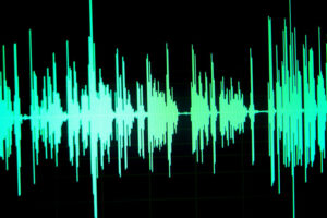
I find that using your voice to create art can be interpreted in many ways. Several people take their experiences and perhaps even struggles and use art to voice their opinions. So while thinking of this idea of using your voice to make art, I began to wonder whether I can design a program to make generative art by using human voice, literally rather than figuratively…
I was wondering whether similar programs have been built before when I stumbled upon an article by Japanese artist Ryoji Ikeda, known for his innovative and contemporary work in the fields of sound art. His project , cyclo.id, in particular, caught my eye. His program focuses on creating circular patterns by the audio’s phase and amplitude and displaying it graphically.
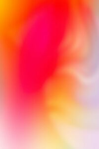
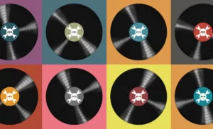
However, I felt as if although the black and white combination really allows us the viewer to focus on the patterns, I personally think that a pop of color is much more fun! That when the idea of warm and cool colors came to my mind. I began to wonder, what if I could take the idea of generative audiovisual patterns, and associate this audio and specifically the volume level to cool and warm color shades. Here are a few pictures of contrasting warm and cool colors I looked at to gain inspiration for my color palette.


Concept:
The SoundWave Constructor is a program that generates an interactive art piece that dynamically responds to audio input from the computer’s microphone every time the program is ran. Every time the user makes noise, the program stores the volume level, and also instantiates a particle every time through the Particle class.

Interestingly, several of the components/attributes of the particle will directly depend on the volume level. For instance, the color of the particle and its trace will depend on whether the volume recorded at that second by p5 is higher or lower than the Threshold. The color of the instantiated particle would be closer to the warmer colors such as the reds, yellows and oranges when the volume recorded is higher than the threshold and closer to the cooler colors such as the blues, purples and greens when the volume recorded is lower than the threshold.

Other factors that depend on the volume include the speed of orbit and the radius of orbit of the particle, and the same idea applies as well, higher/lower volumes constitute to faster/slower speed and larger/smaller radius respectively. I will explain these methods and their implementations in depth in the Code section of this blog post.
How it Started:
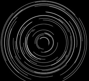
The initial Idea I had in mind was creating almost a digital and audiovisual record player. The way I did that was through creating a very similar particle system and continuously instantiating ellipse particles that also left a trail. Follow along for short descriptions/displays of several programs I tried out before I got to the final program.
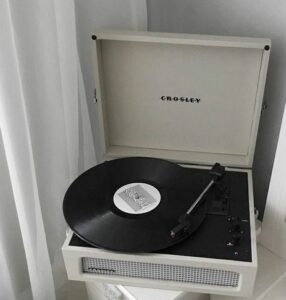
At first, I mainly focused on the instantiation of particles from the particle system. Not focusing on colors, nor speeds, my program lacked a pop of color, but also lacked that generative and creative aspect. Here’s how it looked at that stage:
Next thing I worked on was making sure that based on the volume, the speed of the instantiated particle was determined, and the color as well. Higher volume, faster speed, and brighter colors, lower volume, slower speed, and more dull colors. Snippets of this code and further explanation will be included in the code section.
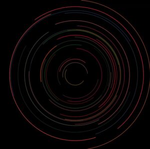
Once I got the speed and color covered, I began to wonder how much more can I push the generative aspect of this program? I began to think of this especially because I noticed that the behavior of these particles are very predictable, and that defies the purpose of generative art! Thats when I began to wonder, how can I play around with trigonometric functions and audio input to make the art less predictable.
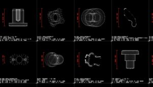
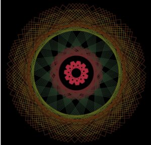
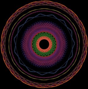
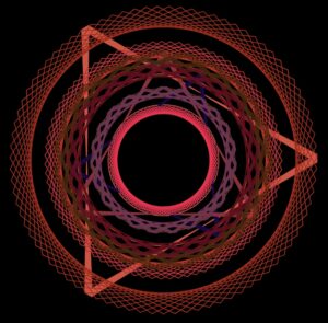
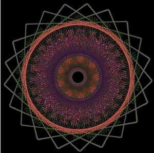
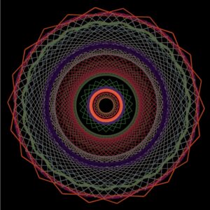
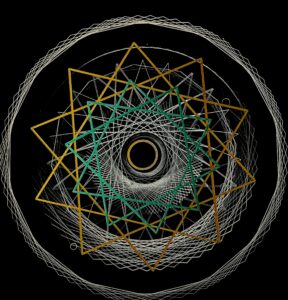
I mainly used trig values to computer the vector’s x and y, and also as part of the particles speed. The way I got the sketches bellow was by randomly switching around the trig values, and also experimenting with rational functions to see the different patterns. Here were a few sketches .
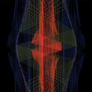
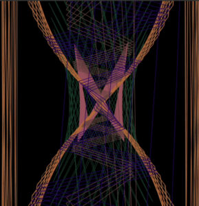
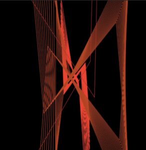
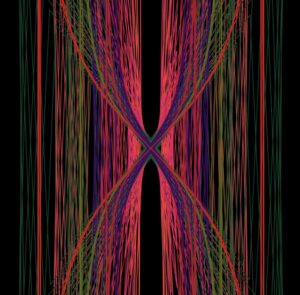
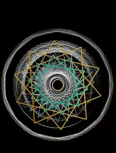
Here are a few sketches I got after fully developing the program:
Tackling Challenges:
The main challenges I faced included editing my code so that it can save an SVG file to be printed on the x, y plotter. At first the SVG would save however it would not open on inkscape. I kept trying various variations in order to get an SVG file that opens on inkscape, but most of them either ran errors or simply did not open.
After following the exact steps on the powerpoint presentation, and revising the syntax for mouse pressed, in addition to trials and errors, I was able to capture an SVG file that looked exactly like my program, and also captured the several layers of the particles and their trails, which was ideal for the printing.
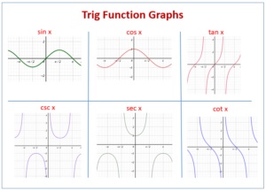
Other challenges I faced included trying to pick which trig value to use as a parameter for vectors’ x and y values, as well as the angle. Playing around with the different trig values gave me several types of patterns, and each combination of trig functions gave a completely different pattern all of which were generative and looked very interesting. It was very difficult to pick one specific pattern, but I found that the combination I used in my final code was very visually pleasing.
To better visualize take a look at the various trig function and their graphs over their period:
One more challenge I faced is leaving the trail on the leading particle. I initially made the leading particle an ellipse, however, I reduced the ellipses size by giving it radius of zero in order to create an illusion of an invisible leading particle. To figure out how to leave the trace, I looked into the update method, and also the create vector method, and combined both to store into the trail history list.
Snippets of Code:
Using Particle System:
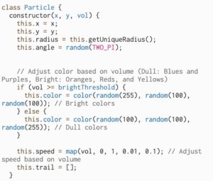
The Particle class is responsible for the individual particles. Each particle is created with a unique radius and a random starting angle, which is then manipulated with other trig functions. The color of the particle is determined based on the volume of the microphone input, with brighter colors for higher volumes. The speed of the particle is also adjusted based on the volume. The position of the particle is updated in the update method, and the path is recorded in the trail array. The display method draws the trail and a very small ellipse, which does not show as its meant to lead the trail, at the current position of the particle.
The ParticleSystem class is responsible for handling a collection of particles. In the update method, it calculates the number of particles to add based on the microphone volume and creates new particles at the specified location. If the number of particles is more than a certain threshold, which is 50 particles, older particles are removed. The display method updates and displays each particle in the system.
Managing Path Direction Through Vectors:
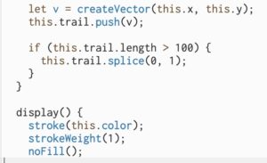
A vector v is created using createVector(this.x, this.y) and it represent the current position of the particle.The vector is then appended to the array this.trail to record the path of the particle. This trail array stores the positions of the particle over time, which later is used to draw the path.The display method of the Particle class uses the this.trail array to draw the path of the particle by connecting the recorded positions using vertex calls, creating a visual trail.
Trigonometric Functions Patterns:
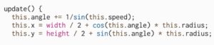
In the update method, the particle’s new x and y coordinates are calculated using trigonometric functions cos and sin. These functions use the this.angle and the particle’s this.radius to get the new position. This.x is calculated as width / 2 + cos(this.angle) * this.radius, which moves the particle horizontally based on the cosine of the angle.this.y is calculated as height / 2 + sin(this.angle) * this.radius, which moves the particle vertically based on the sine of the angle.
FINAL Product:
Note: Please make sure to enable your mic and allow access to run the program using user audio, the link of the program is attached below.
https://editor.p5js.org/ea2749/full/VkTBdCFbK
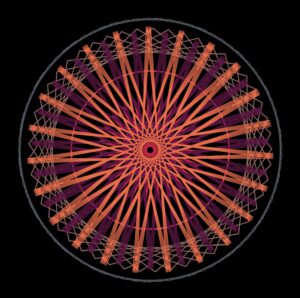
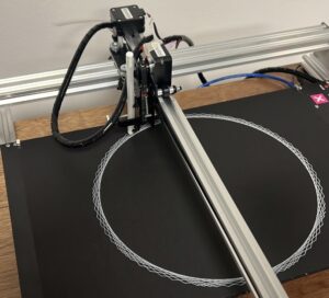
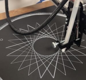
Plotter Sketches:
Reflection and Areas of Improvement:
Creating this p5 program was a very enlightening and fun journey, I most importantly learned how to take the examples, and concepts learned in class and integrate them with one another to create a program that makes generative art. What I enjoyed the most was really trying out all the variations of trig functions I could use to make different patterns, because it allowed me to really visualize how big of an impact switching trig functions can have on our parameters which was the speed and angle.
Although I am satisfied with how my program turned out, I really look forward to further advancing this code and improving certain aspects such as working with more complicated trig functions and visualizing other potential patters. Or perhaps having several different types of particles behave is various ways rather than just one particle in a particle system.