Generative Artistry: Unveiling Creativity through Chaos
Concept
The project, “Generative Artistry,” aims to captivate and engage users by seamlessly transitioning from an interactive Pac-Man-inspired game to a mesmerizing display of generative art. This transition serves as a metaphor for the creative process itself, highlighting the unpredictable and varied approaches artists take to contribute to a shared vision.
Description
Part 1: The Pac-Man Game
Interactive Start
The project begins with a red ball that can be controlled using arrow keys (up, down, left, and right).
The player’s objective is to navigate the red ball to “eat” all the yellow balls, reminiscent of the classic Pac-Man game.
Chaos in Motion
While the player maneuvers the red ball, a couple of yellow balls move randomly, adding an element of unpredictability and challenge to the game.
The dynamic movement and contrasting colors draw players into the experience, encouraging them to participate.
Symbolic Disappearance
Once the red ball successfully consumes all the yellow balls, the Pac-Man game vanishes from the screen.
Part 2: The Generative Art
The Unveiling
After the Pac-Man game disappears, the screen transitions to a canvas where a multitude of small circle balls appear randomly.
These circle balls move unpredictably across the canvas, creating a chaotic yet visually captivating display.
Divergent Colors and Movement
As the circle balls move, they leave a trail behind them in various colors, producing an abstract and seemingly random composition.
Each circle ball represents an “artist,” and their choice of colors and movements is distinct, mirroring the unique perspectives of real-world artists.
Emergence of Shared Art
Over time, as the circle balls continue their movements and mark the canvas with diverse colors, the big picture gradually emerges.
The seemingly disorganized chaos transforms into a cohesive and shared artwork.
Metaphor for Creativity
The project symbolizes the creative process by showcasing how multiple “artists” (represented by the circle balls) contribute their individual perspectives to create a shared artistic vision.
Just as in real life, each artist’s interpretation of the final artwork differs, resulting in a unique and collaborative piece that deviates from the original but retains its essence.
Unexpectedness and Revelation
The project utilizes the element of surprise and gradual revelation, as players initially engage in a game without knowing its deeper artistic significance.
Users only comprehend the full narrative and purpose when the big picture of the generative artwork becomes evident.
Techniques Used
Randomness: Random movement patterns and colors are employed to simulate the unpredictable nature of artistic creativity.
Metaphor: The transition from the game to generative art serves as a metaphor for the creative process, emphasizing the diversity of artistic approaches and outcomes.
Progressive Revelation: Users gradually discover the project’s artistic depth as the generative artwork takes shape over time.
Interactive Elements: User control of the red ball via arrow keys adds an interactive element, making the project engaging and inviting.
Visual Progress
Now finally the “artists” can draw something more realistic and creative as following:
Conclusion
“Generative Artistry” is not just a visually captivating project but also a thought-provoking exploration of the creative process. By seamlessly blending a playful game with generative art, it encourages users to reflect on the nature of art, collaboration, and the beauty that arises from chaos and diversity.
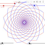
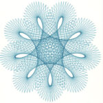
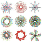
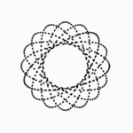
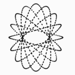
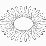
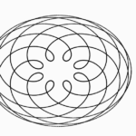
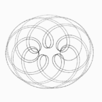
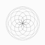
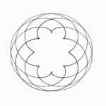
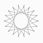
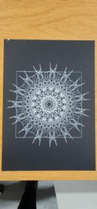
I had decided to switch from my previous sketch as I felt having predefined shapes was too constraining and would not make it generative enough. However, I have still managed to keep it within the same topic as Mandalas. Instead of using predefined shapes, I decided to combine Perlin noise for the randomness and axes of symmetry to create interesting and unique patterns. By lowering the axes of symmetry to 6 or lower, the mandalas begin looking like flowers.
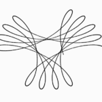
This gave me an idea for the final sketch of the project. I will be making flower objects the same as the below sketch, but spawning them on generated branches, which are also made using Perlin noise.
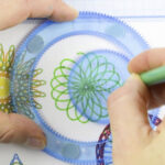
Sketch:
The current sketch is designed specifically for the pen plotter.
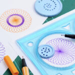
SVGs:
Pen plot:
Next Steps:
I still need to implement the different modes. I’m thinking of offering a simple UI for adjusting the number of axes of symmetry, offsets, and colors of the sketch. This way I would have a high number of combinations a user can achieve with a few sliders.
Develop the random branches that will hold the flowers
I began working on creating a dynamic, 3D terrain that continuously morphs over time. I used WebGL for 3D rendering.
let terrain;
let cols, rows;
let w = 20;
let flying = 0;

function setup() {
  createCanvas(windowWidth, windowHeight, WEBGL);
  cols = floor(width / w);
  rows = floor(height / w);
  terrain = new Terrain(cols, rows);

  // Set the camera position and orientation
  let camX = width / 2;
  let camY = height / 2; // Adjust this value for the desired side view
  let camZ = (height / 2) / tan(PI / 6); // Adjust this value for the desired zoom
  camera(camX, camY, camZ, 0, 0, 0, 0, 1, 0);
}

function draw() {
  background(0);

  // Center the sketch on the canvas
  translate(-width / 2, -height / 2);

  terrain.update();
  terrain.display();
  flying -= 0.05;
}

class Terrain {
  constructor(cols, rows) {
    this.cols = cols;
    this.rows = rows;
    this.w = w;
    this.terrain = [];
  }

  update() {
    let yoff = flying;
    for (let y = 0; y < this.rows; y++) {
      let xoff = 0;
      this.terrain[y] = [];
      for (let x = 0; x < this.cols; x++) {
        this.terrain[y][x] = map(noise(xoff, yoff), 0, 1, -100, 100);
        xoff += 0.2;
      }
      yoff += 0.2;
    }
  }

  display() {
    stroke(255);
    noFill();

    for (let y = 0; y < this.rows - 1; y++) {
      beginShape(TRIANGLE_STRIP);
      for (let x = 0; x < this.cols; x++) {
        vertex(x * this.w, y * this.w, this.terrain[y][x]);
        vertex(x * this.w, (y + 1) * this.w, this.terrain[y + 1][x]);
      }
      endShape();
    }
  }
}
The Terrain class is the core of our terrain generation. It contains methods for updating and displaying the terrain. I want to work on making it aesthetic itself more blocky, since my inspiration for this project is minecraft and I want to replicate its look. I also want to change the colors of the lines depending on their depth, so I can represent land and water.
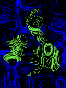
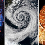
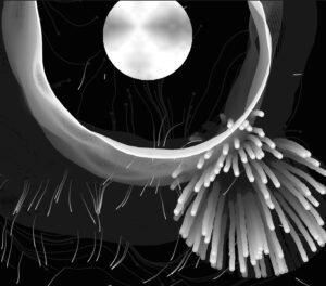
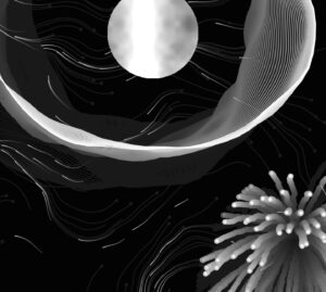
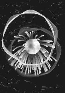
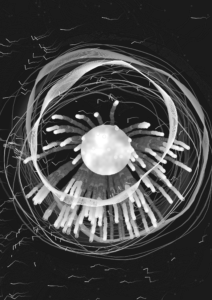
From last post, I have changed many things, either accidentally or intentionally. I am still going with the initial concept of space, but I eliminated a lot of the elements from the original design, such as the hand images, rotating shooting stars, etc. Now, I have four main elements in my code to create the image that I currently have now:
class PerlinShape — expanding circular waves; the patterns that a black hole generates
class particle — perlin noise flow field particles; symbolizes the small stars/shooting stars that we see passing by in the universe
class particle1 — explosion of particles; signifies big stars exploding/being generated in space
ellipse — has perlin noise pattern inside; the “moon”
The ellipse and the perlin noise flow field has mainly stayed the same for the most part since the last progress post, but the two things that I newly developed since then are the exploding particles and the perlin shape waves.
Progress:
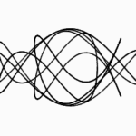
At first, my goal was to create a simple singular circle loop that’s moving using perlin noise, as shown in this tutorial. However, once I implemented the code after modifications, I got a really cool result that looked like one of the images that I originally wanted to create, which were waves like these:
I had some trouble trying to position the ellipse back into the center of the canvas after adding the PerlinShape class into my code, but I realized that once I modified the following snippet below, I was able to get it back to the center:
//circle
let centerX = 20;
let centerY = 20;
let radius = 100;
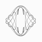
At this point, I had reached this image in my code:
Then, I had to move the explosion of the particles class into the center as well so that they will spring from within the ellipse in the center, for it was positioned at the bottom right corner of the canvas at this point like how it’s shown above.
To do this, I tried adjusting the following part of the code’s x and y positions, but then I ended up with this image:
  // Check if the particle has exceeded the expansion limit
  if (dist(this.position.x*0.8, this.position.y*0.8, width/2, height/2) >= this.expansionLimit) {
    this.lifespan = 0;
  }
}

display() {
  fill(255, this.lifespan);
  ellipse(this.position.x/2, this.position.y/2, 10, 10);
}
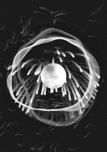
Then I realized that if the value that is multipled to this.position.x and this.position.y are the same throughout in the above code snippet, the particles explode from the center of the ellipse limit that I wanted the particles to expand till, which gave me this image:
Now the only thing I had to do was move this explosion into the center, which I realized was supposed to be controlled from the sketch.js file.
These are the three elements of the code that I made adjustments to in order to control the location of the exploding particles:
let particle1 = new Particle1(width/2, height/2); // Set initial position of the explosion WITHIN the circle boundary
// Check if the particle has exceeded the expansion limit; controlling this elongates the ellipse boundary limit of the particles
if (dist(this.position.x*1, this.position.y*1, width/2, height/2) >= this.expansionLimit) {
  this.lifespan = 0;
}
display() {
  fill(255, this.lifespan);
  ellipse(this.position.x*1, this.position.y*1, 10, 10); // the position of the ellipse limit itself
}
Finally, I kept the this.position.x and this.position.y values consistent so that the particles would expand in a perfect ellipse shape rather than an oval.
Then I adjusted the expansionLimit value so that it’ll expand in a smaller size, and at this point I had this:
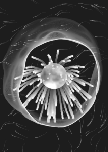
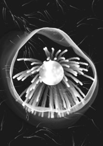
I was pretty happy with what I had by this point, and although a lot of the code ended up being very random and unexpected, I had a lot of fun reaching till this point. A particular feature that I want to highlight is the redrawing of all the elements (perlin noise flow field, perlin noise circle loops, particle explosion, perlin noise pattern of the ellipse) that are on my canvas whenever I click the screen; this helped me generate a lot of interesting and different variations playing with colors, different-shaped lines and waves, directions, etc.
Here are a few different variations that I got:
I might add a few new elements such as stars that will appear in the background or bring back the hand images, etc. Or I might keep it simple like this, haha. But I’d say I’m 90% done with my project!
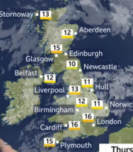
For my midterm project, I want to try and imitate the weather forecast patterns that I would see as a child whenever I watched the news. I was raised in the UK so I primarily saw the weather in the UK but for my midterm, I want to include the countries that mean a lot to me and are different geographically compared to the UK which is an Island. I want to include the UAE as I study there and it is a coastal country, and Afghanistan as it is my home country but also a landlocked country. I think it would be nice to see how different environmental factors looks in these 3 countries as they are geographically different.
Underneath are some images of the news I would see for the UK and I have included some videos to show the kind of image I want to imitate.
Some aspects of this code that I am worried about it working with real life data and having the code perform for a certain amount of time to show the real-time wind. I think it will also be hard to locate my invisible attractors and with the outline of the countries, know where to locate these invisible attractors.
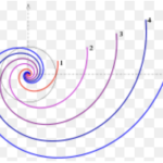
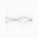
Line animation
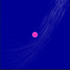
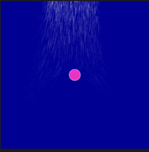
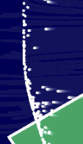
I want to work on having the lines go towards invisible attractors or repel against them. I started off with having a blue background and the lines to imitate the wind to come out of the origin and have the lines be longer. This was just my starting point and I want to add a lifespan for these lines and have them concentrated next to each other. I also wanted to make sure the lines were using the Vector subclass from p5 so I used inheritance.
Now I want to add another attribute that will count as the lines lifetime so that they disappear over time and get popped from the array using splice. I have temporarily made the background black so I can see the white line disappear into the background.
I was looking at different ways to have the white lines be blended into the blue background and found the lerpColour function that did the job for me. I now want to add a single attractor so that my lines can move towards the attractor. Note: I am temporarily having all the code in the sketch.js file to makes it easier for me to create multiple copies of my code for documentation purposes.
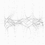
I also wanted to add a single attractor for now just so that I can see what the repel/ attraction would look like. I used the class Attractor from class and modified my Particle class for them to work well together whilst also extending on the p5.js folder. After playing around with the coordinates of the attractor, I ended up with the following effect which I really liked. I also made my canvas size 600 by 600 to see the effect better.
I moved the attractor around and played with the G values and positioning of the lines to be off the canvas so it seems more naturual when it comes and I got this effect.
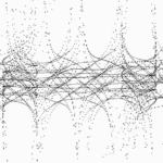
I also need repelling points so I will create an identical class but with a negative G value and I tried to see what it would look like and I really liked the look. I am likely to put these around the borders of the countries.
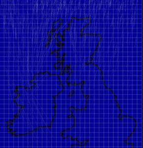
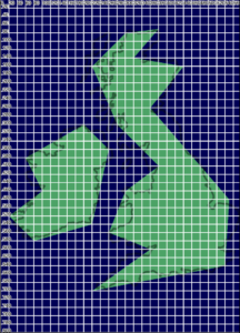
I will now try to find an image of the UK which is just the outline and have the waves be repelled against the borders. I found an image and tried to have some grids placed 20 pixels away from each other to try and see where I would want these attractors and repellers.
let spacing = 20;

  // Draw vertical grid lines
  for (let x = 0; x <= width; x += spacing) {
    line(x, 0, x, height);
  }

  // Draw horizontal grid lines
  for (let y = 0; y <= height; y += spacing) {
    line(0, y, width, y);}
I get the following image so now it is easier for me to see where I need to place my attractors and repellers. I am also going to duplicate my attractor class to create my repeller class. I also need to change the back ground colour or the ocean parts to be green to show a smooth distinction between the mainland and sea – this also includes any major lakes or bodies of water on the mainland.
To do list
have the colour of the water be green/blue – different
figure out the location of the attractors/ repellers
have the wind waves be generated throughout the screen
have the waves through the land go slower
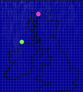
With one attractor and repeller, this is what it currently looks like.
The pink is for the repeller and the green for the attractor.
Some sketches
Second Major Update
So after discussing other methods that I could use to try and create the effect I want, a classmate Xiaozao recommended at looking a force field approach to show a slower, curved and more natural effect. The video underneath is the video that helped me understand how vector fields worked in p5.js and how I can use them effectively to give the effect I wanted.
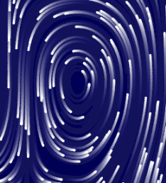
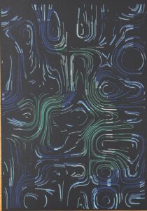
I firstly needed to find a way to create the vector field and luckily the video Xiaozao recommended was a great place to start. From what I had learnt, I know that I needed to have a second ‘background’ and have my centres of attraction generated randomly. We can use Perlin noise to have these randomly generated and also the curl value can really make a difference.
If this value is 1 or above, we will get the following images.
And of its less than 1 and significantly small, we get the following which is a strong attraction and the effect I wanted.
function curl(x, y) {
  const EPSILON = 0.0000001;
  let n1 = noise(x + EPSILON, y);
  let n2 = noise(x - EPSILON, y);
  let cx = (n1 - n2) / (0.9 * EPSILON);

  n1 = noise(x, y + EPSILON);
  n2 = noise(x, y - EPSILON);
  let cy = (n1 - n2) / (0.9 * EPSILON);

  return { x: cy, y: -cx };
}
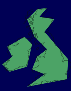
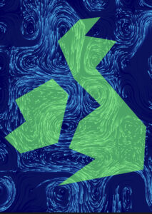
Next thing I decided was to have some image or outline of the UK but trying to get these particular pixels was far too much of a hassle and would end up overcomplicating my code. Instead I decided to have the UK outline drawn out myself into 2 regions and used an image of the UK outline and a grid system to navigate myself to have these points placed.
I also made sure these 2 shapes were saved so I can reference to thew pixels inside those regions.
I wanted to find a way to locate the pixels in these regions as I know I will need to make use of them in the future but as of now, this was my sketch.
INSERT
Plotting
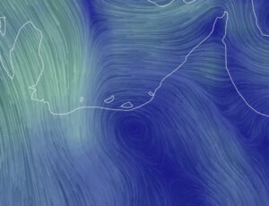
So the next step I took was the plotting and I know I needed to simplify my code to make sure a plot was possible so I implemented a transparent background so that the particles paths were opaque and visible. I also made the background white and had the particles change colour instead, blue if in water and green for land.
I firstly used the following function to check whetehr to not the particle was in the land regions.
function pointInShape(point, shape) {
  // Check if a point is inside a shape defined by an array of vertices
  let oddNodes = false;
  let x = point.x;
  let y = point.y;

  for (let i = 0, j = shape.length - 1; i < shape.length; j = i++) {
    let xi = shape[i].x;
    let yi = shape[i].y;
    let xj = shape[j].x;
    let yj = shape[j].y;

    if ((yi < y && yj >= y) || (yj < y && yi >= y)) {
      if (xi + ((y - yi) / (yj - yi)) * (xj - xi) < x) {
        oddNodes = !oddNodes;
      }
    }
  }

  return oddNodes;
}
This way each individual pixel is checked and can change colour depending on the region. This is what my sketck ended up looking like for my SGV.
While plotting, I realised how much more dimension I wanted and I was able to edit by my SGV on Inkspace and have certain particles removed and have the colour changed. For example, some particles on the green region, I wanted white strokes to represent wind and on the ocean, pastel blue strokes to represent wind and waves.
These are some images and videos of my final plot.
After seeing the additional dimension given in my plot, I wanted to add the same into my final sketch and I made use of the check in region function again and altered the sketch colour accordingly.
// Check if the particle is inside either of the regions
    let inRegion1 = pointInShape(p.pos, region1);
    let inRegion2 = pointInShape(p.pos, region2);

    if (inRegion1 || inRegion2) {
      // stroke(255); // White line
      stroke(110, 245, 137);
    } else {
      stroke(8, 196, 252);
      // stroke(139, 222, 247); // Pastel blue color
    }

    point(p.pos.x, p.pos.y);
  }
A final touch I added was some sound representing the wind and I though it went nicely with the movement of the particles and gave it that final missing touch.
Future Changes
Next time, I would like to have my other countries included. I realised through my project that I would not be able to show the other countries as well as they are not islands. I would also like to make this model in 3D so it is like the website example I was provided with. I also realised after time, the particles would almost disappear, I liked it initially but I wish they would regain speed after some time.
In today’s age, climate change remains one of our most pressing concerns, and our role as humans in this issue is undeniable. This generative art project aims to convey this message, highlighting our influence on our environment.
The dynamic waves in the visualization, expanding outwards when the mouse is pressed, are symbolic of the rising sea levels. At the heart of the piece lies a yellow circle – the sun, representing hope and the promise of a new day. Placing the sun in the center implies that despite the dangers and challenges, there’s a core of hope and a chance for a new beginning. This balances the alarming nature of the design with optimism.
The colors of the waves transition from blue to green to brown, encompassing the elements of water, vegetation, and the desert, paying homage to the UAE’s natural landscapes as it hosts the 2023 COP convention. COP – or Conference of Parties- is an annual global conference under the United Nations that brings together nations to discuss and advance international responses to climate change.
The waves do not move in a smooth, organized, calm manner. Instead, they are overlapping, some have bigger amplitudes than others and their speed increases over time. This creates a chaotic motion, representing the uncertain and messy reality of climate change.
In my opinion, the most important aspect of this piece is its interactivity. The fact that the user, through their control of the mouse, directly influences the expansion of the waves and the size of the sun highlights the significant role humans play in the climate crisis. Whether we’re causing the sea levels to rise or projecting more hope for the future, the power is quite literally in our hands. This concept is further reinforced with the text embedded within the sketch “The future is in your hands”, emphasizing that every action counts.
The design of this project was partly inspired by this animation by @mr_praline on Instagram.
Embedded Code
Future Direction:
1) I want to enhance the immersive experience by integrating sound – maybe a gentle lapping of waves or the whistles of wind.
2) I want the piece to reinforce its homage to the UAE. An idea is to outline UAE landmarks at the bottom of the sketch, perhaps the Burj Khalifa.
3) Emphasize the desert more by creating sand particles being blown off the dunes, maybe through the emitters we learned in Particle Systems
4) Add a drag force to the waves to represent water undercurrents
5) Maybe introduce aquatic creatures as random walkers
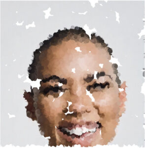
This documentation explores a creative generative art project developed using p5.js. The project involves generating unique and visually appealing artwork based on a given input image. The art is created by employing a combination of random walkers that traverse the canvas, averaging pixel colors, and providing a real-time drawing effect.
1.2 Objective
The primary objective of this project is to harness the potential of generative algorithms to transform an input image into a distinctive and visually intriguing artwork. By utilizing random walkers and pixel color averaging, this project aims to offer a creative and dynamic approach to image interpretation.
1.3 Creative Approach
The project’s creativity lies in its unique amalgamation of pixel color manipulation and random walker behavior. Instead of a straightforward one-to-one mapping of image pixels, the art is generated by iteratively averaging the colors of neighboring pixels. Additionally, the art’s dynamism is achieved through the use of random walkers that contribute to the image in real-time, giving it a captivating and evolving appearance.
2. Getting Started
2.1 Setting Up p5.js
To begin, ensure you have p5.js set up in your development environment. You can download the p5.js library from the official website (https://p5js.org/). Follow the installation instructions provided on the website.
2.2 Importing the Image
Start by importing the image you wish to transform creatively into your p5.js sketch. You can use the loadImage() function to load the image and display it on the canvas.
2.3 Initializing the Random Walkers
Create random walkers that will move across the canvas. Each walker’s behavior and appearance can be customized according to your creative vision. Initialize these walkers with random starting positions and directions.
3. The Generative Process
3.1 Pixel Color Averaging
The core of this project’s creativity lies in pixel color averaging. Instead of mapping image pixel colors one-to-one, calculate the average color of a pixel’s neighborhood (e.g., a 3×3 or 5×5 grid of surrounding pixels). This technique introduces a smoothing effect and adds uniqueness to the generated artwork.
3.2 Random Walkers
The random walkers contribute to the creative process by traversing the canvas and drawing pixel colors. Customize the walker’s step size, direction changes, and color selection. The random nature of the walkers ensures that each run generates a distinct artwork.
3.3 Real-time Drawing Effect
The magic happens when the walkers contribute to the drawing of the image in real-time. As walkers move across the canvas, they apply the averaged colors to the corresponding pixel locations. This real-time interaction creates an intriguing and dynamic visual effect as if the image is being drawn before your eyes.
4. Enhancing Creativity
4.1 Adjusting Walker Behavior
Experiment with different walker behaviors to achieve a variety of artistic effects. You can control parameters such as step size, direction changes, and the duration of each walker’s journey.
4.2 Modifying Averaging Techniques
Tweak the pixel color averaging technique by adjusting the size and shape of the pixel neighborhood used for averaging. Experimenting with different neighborhood sizes and shapes can yield diverse visual outcomes.
4.3 Experimenting with Color
Explore the creative potential of color by experimenting with different color schemes, blending modes, or even introducing random variations in color selection for each walker. This allows for further artistic expression.
5. Conclusion
5.1 Final Artwork
Upon completing your generative art project, you will have a unique and visually captivating piece of artwork that creatively transforms the input image.
5.2 Future Improvements
Consider future enhancements, such as optimizing performance, adding interactivity, or integrating additional creative elements into your project.
5.3 Acknowledgments
Give credit to any resources, libraries, or individuals who have inspired or contributed to your project. Acknowledging your sources is essential in the world of creative coding.
In summary, this documentation provides a comprehensive overview of the generative art project created using p5.js. By creatively combining random walkers, pixel color averaging, and real-time drawing, you can produce dynamic and visually appealing artworks that showcase the power of generative algorithms in the world of art and creativity.
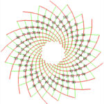
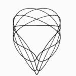
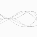
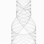
My inspiration for this week’s assignment was the artist we looked at in class last week – Memo Akten. His work, The Awesome Machinery of Nature, was quite fascinating. I wanted to create a similar effect to that with circles coming out of a circle and colliding and creating a ripple effect. Since the motion was periodic (with some variation) I thought of modelling it with functions of sin and cosine for this week’s SHM project. Let’s see how that went.
MY PROCESS
I started with first trying to align all dots in a circles and alter their individual movements by changing their radius in a periodic motion modelled by sin and cosine. There are the first few attempts looked like this:
By playing around with the period, phase difference, and timeOffset parameters, I saw interesting patterns:
Half a wave with so much as corners:
2 breathing circle and semicircle patterns with only one wave! Not two!!
In the above one, It looks like the semicircles are in a relay race, passing the baton.
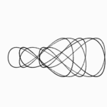
Playing around with the parameters of this, I got something more interesting:
More intricate:
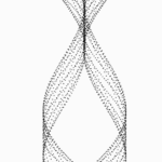
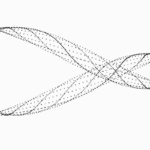
Yes, I kind of branched out way too much here and lost focus of what I started with. But before I redirected my focus into creating something similar to Memo Akten’s work, I wanted to try one more thing. Trying to create a standing wave. What we practiced in class, looked like a sin wave going sideways, I did not want that, but rather the particles to oscillate in the same place – I kind of said the same thing didn’t I? Yes, but visually it looks different. For example:
Here is a bouncing sin wave appearing to move towards the left:
But now, below is the same sin wave but bouncing in its position (notice the leftmost point does not move / stays in its place – called a node in physics):
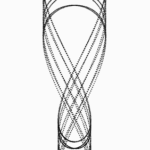
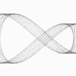
Now combining all of this, I set out to create an SHM hypnosis like artwork for this week’s coding assignment. Below are the various iterations and versions of it:
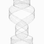
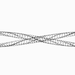
By playing around with the wavelength and phase difference, I got this illusion of the full disk/plate moving.
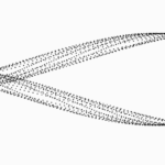
By employing prime numbers like 23, 41, 43 (in order for below sketches), I got this breathing kind of illusion – but fragmented, instead of a full circle.
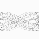
By adding multiple sin waves (superposition of waves), I was able to make this amoeba style effect.
TECHNICAL DESIGN AND CODE
So the main piece of code that influences all of this is the following:
let y1 = (map(sin(angle+phaseDiff*i*wave2_offeset), -1, 1, radius-50, radius+50));
let y2 = (map(sin(angle+phaseDiff*i*wave2_offeset), -1, 1, radius-50, radius+50));

let y = (y1 + y2)/2; // to not have the amplitude v high - scaling it down

let x = map(i, 0, num, 0, TWO_PI);

stroke(255);
line(0, 0, y*cos(x*offset), y*sin(x*offset)); // draw the circles in circlular fashion instead of linear

fill(red, g, b);
circle(x*offset, y, radius*2); // draw the actual circles

let r = map(sin(angle+phaseDiff*i), -1, 1, 5, 15); // radius of outer circle varies slightly each loop -> to create breathing effect

// update angle
I have 2 sin waves superimposed which gives this jelly-like effect of the moving circles (in contrast to the first example which was achieved solely by one sin wave). Then the key is the wave_offset and the particle offset which create the phase difference and the periodic motion between the particles. changing the position of the offset in the equation also changes the appearance from bring a standing wave to a moving wave.
The various parameters used above are initialised are such:
let offset = 4; // try n = 21, 23, 41, 43, 27, 10, 2, 1
let angle = 0;
let num, period, phaseDiff;
let radius = 100, t= 0;
let wave2_offeset;

function setup() {
  createCanvas(400, 400);
  num = width/offset;
  // radius = offset/2;
  period = num/2;
  phaseDiff = TWO_PI/period;
  wave2_offeset = PI; // try option PI/2, 2, 5 etc.
}
By playing around with the above parameter values, we get varied results as shown above.
FURTHER DEVELOPMENTS
I believe this design and idea has a lot of potential. I could make a couple of such circles to look like fireworks. Or develop it sequentially to do tasks one after the other. Or make it oscillate based on sound. Many aesthetic and conceptual things might be achieve with this preliminary idea.
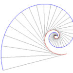
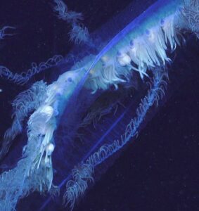
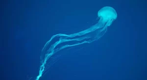
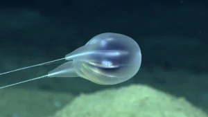
For my midterm project I plan on creating a design that reflects life under water and produces abstract shapes that mimic the possible look and movement nature of unknown species. I aim to create a visually pleasing design that combines gradients of color with constantly evolving floating shapes to showcase the beauty while also sparking curiosity about what lies under the surface of the ocean. To further amplify the experience I plan on adding sound effects or music tracks that would allow for the design to be more immersive.
Process:
I began researching and attempting certain approaches to achieve my intended goal:
My first step was to look into how I could create the shapes that look like underwater species. For that I had to put in mind the gravity force that affects the species underwater, and the need to achieve a floating/ undulating movement effect on the shapes. Similar to what I had done in my last assignment, I could possibly create that through using Perlin noise to affect the position of the shapes over time. Perlin noise could also be introduced when creating the lines that formulate my shape. In doing so, I will be able to achieve a smooth moving surface for the creatures. Another thing I am looking into is introducing noise into the RGB values to have a smooth change of color over time.
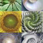
However, I am still unsure of how I could be creating shapes that are constantly evolving while still looking like underwater creatures. I thought of starting off with a circle of lines. These line could be randomized in amount and position using noise. From there I’ll be able to create a floating circle-like shape. But when it comes to having this shape change I will have to introduce some mathematics into the structure of the circle itself. I looked through some tutorials, and one that inspired is below. It shows how to create a constantly looping circle that is in the shape of a mathematical cardioid shape.
I am still learning more about how to apply this to my shapes, perhaps by creating different anchor points to the lines other than just the center of the circle I could get somewhere. Once I am able to create these evolving shapes I plan on putting them into a class to play with the frequency and number of which they appear on screen. I also am hoping to include forces of attraction/ repulsion between the shapes and add introduce acceleration like we did with the movers to make an even more realistic underwater environment.
One other thing I hope to apply is have the background look like its a water rather than just blank. When searching into that I found that patterned surfaces like rough floors could be achieved through what is called Worley noise, similar in its use but different in its outcome than Perlin noise. Below is the video I began exploring and hopefully relying on that and other tutorials ill be able to achieve the desired effect.


 UAE / Gulf
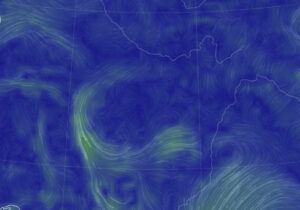 Afghanistan / Central Asia
 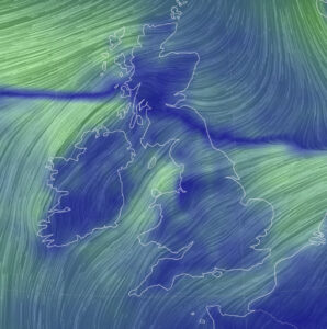 UK
UK