Final Project – 3D Procedural Creature Generator

https://editor.p5js.org/oae233/full/lk6Id6oVL

Concept / Idea

In my midterm, I recreated the visual components of the body using & coding logic and used them as the “paint” to create my artwork, in an attempt to explore the concept of the body. For my final I wanted to focus on the aspect of recreating bodies in 3D space, trying to replicate the biological logic behind how they are assembled. I broke down different parts of the body that are shared among a variety of creatures and thought about how to recreate them, with varying attributes that produce both familiar and wildly new forms.

I hope that my project can leave users with a sense of connectedness with different life forms no matter how physically different we might be.

Implementation:

For this project, I implemented my knowledge gained from the course about using randomness, noise, oscillation/waves, class handling, and trigonometry logic.

I start by generating points in 3D space and then draw lines to connect them. this creates the skeleton or base of my creature. Then I use points on these lines to place different 3D primitives, orienting them based on the lines’ direction.

I only implemented this idea to the spine (which creates the main body) and arms and legs.

Some code I want to highlight:

ThreeD(i) {
    // push();
    // this.radius2 = this.radius1/(i+1);
    this.length = p5.Vector.sub(this.startPoint, this.endPoint);
    this.nextlength = p5.Vector.sub(this.nextstartPoint, this.nextendPoint);

    this.distance = p5.Vector.dist(this.startPoint, this.endPoint);
    this.division = this.distance / 2;
    this.lengthStep = p5.Vector.div(this.length, this.division);
    this.facing = this.length.heading();
    this.nextfacing = this.nextlength.heading();

    this.anglediff = this.facing - this.nextfacing;

    this.anglediff /= this.division;
    // this.counter+=0.5;

    for (let w = 0; w <= this.division; w++) {
      this.sinwav = map(i, 0, this.bodyparts, 0, 90);
      this.counter += 0.04;
      // this.radius2 = this.radius1/this.counter;
      this.radius2 =
        (this.radius1 / this.counter) *
          this.Rmax *
          cos(this.shift + this.sinwav * this.stretch) +
        this.Rmin;
      this.radius2 = constrain(this.radius2, 2, 100);
      push();
      noStroke();
      translate(
        this.startPoint.x - this.lengthStep.x * w,
        this.startPoint.y - this.lengthStep.y * w,
        this.startPoint.z - this.lengthStep.z * w
      );
      rotate(90);
      rotate(this.facing);
      cylinder(this.radius2, 5);
      pop();
      if (w > this.division - 1) {
        for (let z = 0; z < this.division; z++) {
          push();
          // print(z);
          noStroke();
          translate(
            this.startPoint.x - this.lengthStep.x * w,
            this.startPoint.y - this.lengthStep.y * w,
            this.startPoint.z - this.lengthStep.z * w
          );
          rotate(90);

          rotate(this.facing - this.anglediff * z);
          cylinder(this.radius2, 5);
          pop();
        }
      }
    }
  }
}

This is the function that turns the line skeletons into 3D shapes. As u can see I use the length of the line (this.distance) to distribute the shapes at constant density across all lines.

I also modulate the radius using various waves to create variation.

Happy Accidents:

Tip: use your mouse to move around this shape!


IM Showcase:

Future work:

For future work I’d love to complete the project, adding support for heads, and individual facial features like mouth and eyes, that can generate vastly different forms from beaks and simple eyes, to toothful jaws and compound eyes. This was what I had hoped to do in the beginning but unfortunately I was unable to complete it on time.

Black hole dynamic

Final Project: Dynamic of 2 supermassive blackhole

Inspiration
This project delves into the intricacies of simulating black holes’ gravitational influence on particles in a 2D space. Inspired by coding train and supermassive black hole and chaos behavior in astronophysic. With the music from rock band supermassive black hole, I would like to make an art with colorful trajectory created by the photons passing black holes

Techniques from decoding nature course
In this project, I use the knowledge I learnt from particle system, force and autonomous agent, as well as object orient programming. And the interaction part lies in the mouseclick and the operation of blackhole class and particle release and music start as the key board press.

Basic Setup
The setup() function initializes the canvas and GUI interface, allowing users to manipulate parameters such as black hole types, gravitational constant, particle count, and reset functionality.

let easycam;
let particles = [];
let blackHoles = [];
let controls = {
  type: 'Cylinder',
  c: 30,
  G: 6,
  m: 5000,
  Reset: function () {
    particles = [];
    blackHoles = [];
    initSketch();
  },
};

let pCount = 4000;
let lastTapTime = 0;
let lastTapPos;
let bgMusic;

Class of blackholes

Utilizing the Blackhole class, we represent black holes on the canvas based on their mass and Schwarzschild radius. The visualization showcases their gravitational influence by affecting the trajectories of nearby particles.

class Blackhole {
  constructor(x, y, m) {
    this.pos = createVector(x, y);
    this.mass = m;
    this.rs = (2 * controls.G * this.mass) / (controls.c * controls.c);
  }

  pull(photon) {
    const force = p5.Vector.sub(this.pos, photon.pos);
    const r = force.mag();
    const fg = (controls.G * this.mass) / (r * r);
    force.setMag(fg);
    photon.vel.add(force);
    photon.vel.setMag(controls.c);

    if (r < this.rs) {
      photon.stop();
    }
  }


Particle Behavior:
The Particle class defines particle behavior, including position, velocity, history of movement, and their interaction with black holes. Each particle’s trajectory is influenced by gravitational forces exerted by the black holes, leading to dynamic and visually engaging movements.

class Particle {
  constructor(pos, particleColor) {
    this.pos = pos;
    this.vel = p5.Vector.random2D();
    this.vel.setMag(controls.c);
    this.history = [];
    this.stopped = false;
    this.particleColor = particleColor; // Store the color of the particle
  }

  stop() {
    this.stopped = true;
  }

  update() {
    if (!this.stopped) {
      this.pos.add(this.vel);
      let v = createVector(this.pos.x, this.pos.y);
      this.history.push(v);
      if (this.history.length > 100) {
        this.history.splice(0, 1);
      }
    }
  }


Interactive Controls and Rendering:
Our project features an intuitive GUI interface allowing users to dynamically modify parameters, alter particle behavior, and manipulate black hole properties in real-time. This interactivity enhances user engagement and facilitates a deeper understanding of black hole dynamics.

  
  canvas.mouseClicked(addBlackHole);
}
function addBlackHole() {
  const currentTime = millis();
  const mousePos = createVector(mouseX - width / 2, mouseY - height / 2); if (currentTime - lastTapTime < 300 && dist(mousePos.x, mousePos.y, lastTapPos.x, lastTapPos.y) < 50) {
    // Double tap detected within 300ms and close proximity
    particles.push(new Particle(mousePos, color(random(255), random(255), random(255))));
  } else {
    
    blackHoles.push(new Blackhole(mouseX, mouseY, random(5000, 10000)));
  }

  lastTapTime = currentTime;
  lastTapPos = mousePos;
}


Physic logic behind particle and blackhole setup
newton second law and relativity

Final Project Summary + Last Progress

Concept:

My concept actually came from my recent obsession of a Korean historic drama series. I always harbored huge passion in the traditional art of Korea because my childhood consisted of visiting museums and palaces in Seoul, so the traditional arts and music of Korea was always dear to my heart. Last year in my Intro to IM class, I wanted to recreate the Korean traditional patterns for my final project, but because I had limited knowledge in p5.js back then compared to now, I gave up the idea. However, this time, I wanted to challenge myself and make my project based on this, especially while I felt motivated to do so because I was obsessed with a historical drama.

Another feature that I wanted to implement for a long time was having users be able to manipulate audio as well, and this gave me the idea of the final project I came up with, which was: having the users control and create their own visual and music by having both the sketch and the audio be interactive with the theme of introducing the Korean traditional art.

I thought it’d be easier to show Korean traditional art if I could have a basic “background layout” for both the audio and visual aspect.

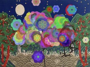
For the visual aspect, I decided to have a backdrop of a Korean traditional landscape that is called Irworobongdo, which is a folding screen with peaks, sun, moon, etc. painted on it that was set behind the king’s throne during the Joseon dynasty, and have different coded aspects such as flowers, trees, fireflies, etc. “grow” or be added on top of that background.

As for the audio, I decided to use a Korean traditional song named 比翼連里, because I thought the melody and the general atmosphere fits the visuals of my sketch well.

Process:

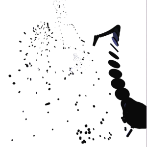
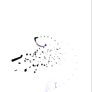
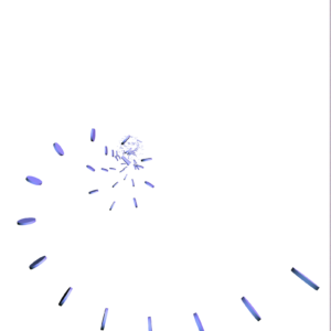
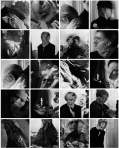
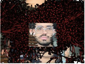
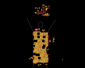
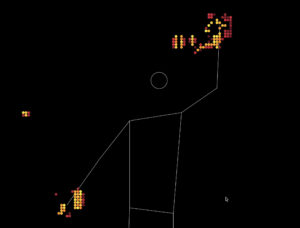
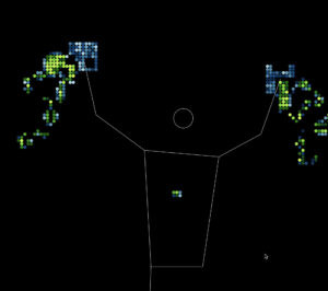
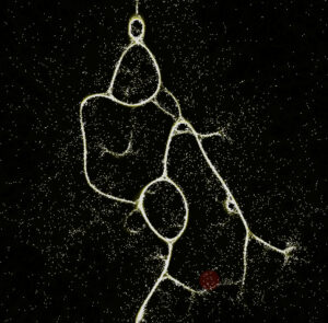
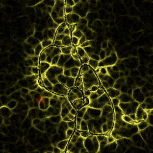
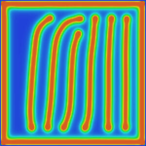
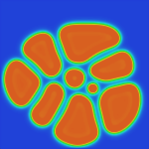
Here are a few different images of various renditions I tried out before settling with my final concept and sketch:

I also included all the trials I’ve tried in detail in my last post, which you can read here.

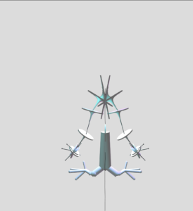
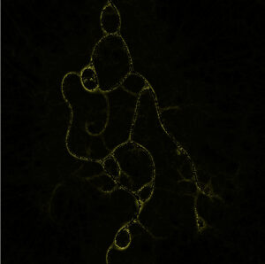
The final sketch layout I settled with last week was this:

After I settled on the basic layout of my sketch, I set out to make progress from my previous post’s sketch progress, for which I did the following:

  • Making the branches so that they won’t grow to be that long (I don’t really like how long they’re growing because it loses its original shape) –> I adjusted the below code snippet to 0.7 from 0.9 to decrease the lengths of the branches A and B.
branchA() {
  let dir = p5.Vector.sub(this.end, this.begin);
  dir.rotate(PI / 4);
  dir.mult(0.7); // adjust this to adjust the lengths of the branches
  • Implementing audio files and linking them to the keyboard –> multiple different snippets of sound from varying traditional instruments that are triggered by different keys on the keyboard, so that they form a harmony as the user generates more flowers onto the canvas. This was honestly the most important and urgent feature that I was nervous to experiment with, for I wasn’t sure how it was going to work because I never tried it before.

Here are the audio files that I’ve used:

The main track that plays when the sketch opens

Sound of janggu (I added two versions of this)

Sound of percussion triangle

Sound of rainstick

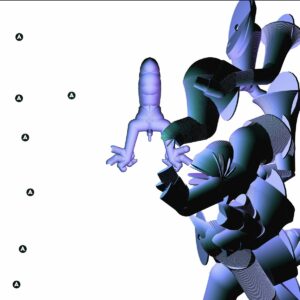
I first made a demo sketch before implementing it into my actual sketch because I wanted to focus on testing the audio only; below is the demo sketch with each A, B, C, D, and E key triggering respective audio files:

(you can try pressing the canvas once first, and then press any of the A, B, C, D, E keys on your keyboard, and make sure they’re capitalized when you do so. doing so will play the corresponding audio.)

A code highlight of this demo was the function keyPressed () and the details that I learned to implement inside this function.

function keyPressed() {
  // Check if the key corresponds to a loaded audio file
  if (key === 'A') {
    // Play or stop the audio file based on its current state
    if (A.isPlaying()) {
      A.stop();
    } else {
      A.play();
    }
  } else if (key === 'B') {
    if (B.isPlaying()) {
      B.stop();
    } else {
      B.play();
    }

Because I wanted the users to be able to control the sounds, I implemented the if/else function so that once the key was pressed once, the audio will play, and when pressed again, it’ll pause.

Once this was done and I was sure it’ll work smoothly, I added the code to my actual sketch.

After this, I decided that adding a page of instructions in my code will be helpful, so I wrote the basic instructions and had it appear before the actual sketch began running. For this, I took my last year’s Intro to IM final project code’s homepage portion and changed the properties accordingly, which was the code snippet below:

// Declare variables for home screen
let startButton;

// Initialize home screen
function initializeHomeScreen() {
  // Create start button
  startButton = createButton('Start');
  startButton.position(width / 2 - 30 , height -250);
  startButton.mousePressed(startMainCode);
}

// Draw home screen
function drawHomeScreen() {
  background(255); // Set background color for home screen
  textSize(15);
  fill(0);
  textAlign(CENTER, CENTER);
  
  // Display instructions
  let textY = height / 4;
  text('Welcome! Here are some basic instructions before you begin:', width / 2, textY);
...(REST OF THE INSTRUCTIONS)
  
  startButton.show();
}

12/7 In-Class User Testing & Progress Since Then:

Here are suggestions I got from my classmates during the Thursday class, which I thought were very helpful:

  • Give more options for background 

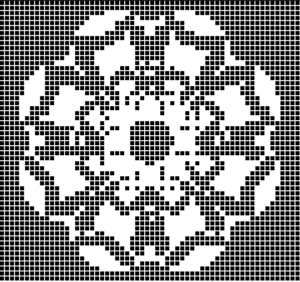
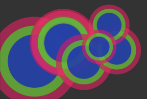
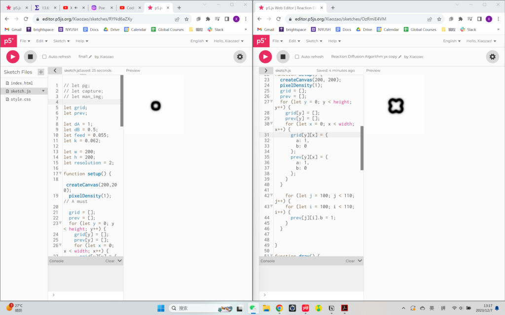
I thought this was a neat idea, and I decided to give another background option that users could manipulate via sliders. Xiaozao gave an idea of having one of the background options being a coded background, so from this idea I developed a code of pixelated sunset in which users could control the colors of the sunset using sliders. Here’s the sketch I’ve created as a demo using this sample image:

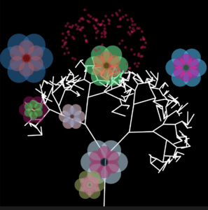
However, when I implemented this code into my sketch, it didn’t exactly give an outlook that I wanted; I also noticed that the sketch was running slower, which I wanted to avoid. At this point, my sketch was like this:
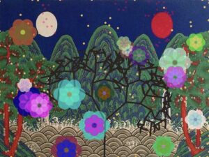
I still wanted to give two options for the backdrop, but instead of coding the background, I decided to give two image backdrop options instead. The idea of having the second backdrop as a modern landscape of Korea came unexpectedly, and I thought this would be a fun comparison to draw! Therefore, I created a toggle button that could switch the background image at mouse click, and added another landscape image from this link. After adjusting the toggle button to the bottom right corner, I had this sketch:

  • Idea i had: when mouse is pressed, flowers keep being generated

For this, I added a new function called mouseDragged(), which made it so that once the mouse is pressed and dragged across the canvas, it continuously generates multiple flowers, as shown in the image below.

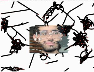
  • Adjust the particles (their positions, number, repelling distance, etc.)

For this, I adjusted the “flee(target)” aspect, the “update()” aspect inside the function particle, as well as “function initializeMainCode()” to 1) increase the number of particles, 2) limit the particles to the upper half of the canvas, and 3) make the repelling of the particles more clear.

  • SVG file export –> Screenshot feature

Lukrecija suggested this idea, and I thought this was so clever. However, I thought adding a screenshot feature might be easier than SVG file export feature, because I remember the SVG feature making my sketch lag a lot last time during my midterm project.

For this, I also created a button named “Take Screenshot,” and added the following code snippet after declaring the screenshotButton as a variable and adding the button in the function initializeMainCode():

function takeScreenshot() {
  // Save the current canvas as an image
  saveCanvas('screenshot', 'png');
}

Once I had the finalized sketch, I just adjusted it to go into full screen mode, and I was good to go!
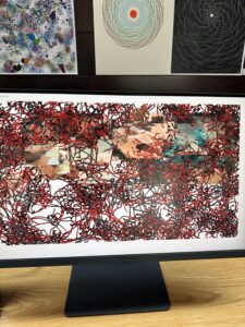
Final Sketch:

Implementation: 

The interactive aspects of this sketch are the following:

  • Particles — used steering, fleeing, wandering, etc.; the user can hover the mouse nearby the particles, and they will see that particles are repelling the mouse.

Code snippet:

flee(target) {
  let desired = p5.Vector.sub(this.position, target);
  let d = desired.mag();

  if (d < 150) {
    // Normalize the desired vector
    desired.normalize();

    // Set a fixed magnitude for consistent repelling force
    let repelMagnitude = 10; // Adjust the repelling force as needed

    // Scale the vector to the fixed magnitude
    desired.mult(repelMagnitude);

    let steer = p5.Vector.sub(desired, this.velocity);
    steer.limit(this.maxSpeed);
    this.applyForce(steer);
  }
}

This is the fleeing behavior that I added in the class Particle, and this was the main feature that I kept changing in the particle class in order to get the desired speed and distance of the particles’ repelling behavior.

  • Flowers — flowers will grow on canvas per mouse click, and there’s two options for the users: 1) one single mouse click — one flower generated, 2) keeping the mouse pressed on the canvas — multiple flowers continuing to be generated.

Code snippet:

function mousePressed() {
  if (currentPatternIndex === 0) {
    let flower = new KoreanFlower(mouseX, mouseY);
    flowers.push(flower);
    patterns.push(flower);
  } else if (currentPatternIndex === 1) {
    let tree = new FractalTree(mouseX, mouseY);
    patterns.push(tree);

    // Generate additional flowers around the tree
    for (let i = 0; i < 10; i++) {
      let flower = new KoreanFlower(tree.x + random(-50, 50), tree.y + random(-50, 50));
      flowers.push(flower);
      patterns.push(flower);
    }
  }
}

The function mousePressed() generates one flower per mouse click.

function mouseDragged() {
  // Check if the mouse is continuously pressed
  if (mouseIsPressed) {
    // Generate a flower at the current mouse position
    if (currentPatternIndex === 0) {
      let flower = new KoreanFlower(mouseX, mouseY);
      flowers.push(flower);
      patterns.push(flower);
    }
  }
}

The function mouseDragged() generates multiple flowers as you drag the mouse on the canvas while it’s pressed.

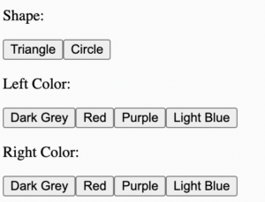
  • Background — users can choose between gradient background/image background, which they can choose by using buttons below the canvas; they can also adjust the colors of the gradient using sliders.

Code snippet:

let backgroundImage1;
let backgroundImage2;
let currentBackgroundImage;

I first declared both images as a variable, and I also set the first background image (the traditional painting) as the initial background image.

function toggleBackground() {
  // Toggle between the two background images
  if (currentBackgroundImage === backgroundImage1) {
    currentBackgroundImage = backgroundImage2;
  } else {
    currentBackgroundImage = backgroundImage1;
  }
}

A key feature of the background images was the toggleBackground function, which was a new feature I tried implementing in my code! This allowed me to go back and forth between the two backdrops with least difficulty as possible.

  • Audio — users can use the keyboard keys A, B, C, D, and E to mix and play the different audio files as they wish, thus generate a music of their own.

Code snippet:

// declare audio files
let A;
let B;
let C;
let D;
let E;

...

function preload() {

...
    // Load audio files
  A = loadSound('A.MP3');
  B = loadSound('B.MP3');
  C = loadSound('C.MP3');
  D = loadSound('D.MP3');
  E = loadSound('E.MP3');
}

I first uploaded, called, and declared them.

// for audio files
function keyPressed() {
  // Check if the key corresponds to a loaded audio file
  if (key === 'A') {
    // Play or stop the audio file based on its current state
    if (A.isPlaying()) {
      A.stop();
    } else {
      A.play();
    }
  } else if (key === 'B') {
    if (B.isPlaying()) {
      B.stop();
    } else {
      B.play();
    }
  } else if (key === 'C') {
    // Play or stop the audio file associated with the 'C' key
    if (C.isPlaying()) {
      C.stop();
    } else {
      C.play();
    }
  } else if (key === 'D') {
    // Play or stop the audio file associated with the 'D' key
    if (D.isPlaying()) {
      D.stop();
    } else {
      D.play();
    }
  } else if (key === 'E') {
    // Play or stop the audio file associated with the 'E' key
    if (E.isPlaying()) {
      E.stop();
    } else {
      E.play();
    }
  }
}

Then, I created a function keyPressed() specially for the audio files, where I linked each key to an audio file and established the playing and stopping functions on first and second click, respectively.

Links Used: 

I watched a few tutorials such as the following (video1, video2, video3) for various parts of my sketch, whether it be the gradient background, creating a fractal tree, or implementing audio into my sketch. All the other images/audios I’ve used were linked either in the previous post or in the other parts of this post.

Parts I’m Proud Of:

Honestly, I’m very proud of the entire sketch without a particular part that I’m especially fond of, for I think it’s very packed with different details, options, and functions because I hoped to provide as many variations for the users as possible so that they can have as much creative freedom as they wish. I still think I’m the most proud of successfully having both the visual sketch and the audio music be manipulated by the user using methods such as sliders, keyboard, and the mouse, making the entire sketch be an embodiment of interactivity.

I also had many new features I tried out, such as toggle background and take screenshot functions. I was also proud of running them smoothly in my sketch as well!

Challenges:

Something I struggled with for a long time was loading the audio files and having them play, because I couldn’t figure out why the sketch kept having error messages for a long time; it turned out that it was because I didn’t capitalize the “.mp3” part of the audio file names when I wrote it in the code. It was one of those “ah-ha” moments with p5.js and being extra cautious with the details, haha.

function preload() {
  // Load audio files
  A = loadSound('A.MP3');
  B = loadSound('B.MP3');
  C = loadSound('C.MP3');
  D = loadSound('D.MP3');
  E = loadSound('E.MP3');
}

I also struggled with implementing a coded pixelated sunset background, for I had many different difficulties every time I tried a new method; for example, the canvas was recognizing the gradient and original background buttons as just simply mouse pressing against the sketch, which was triggering the multiple generations of flowers instead of having the buttons be pressed and switch the background.

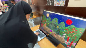
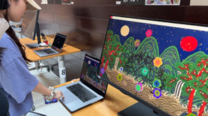
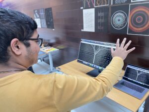
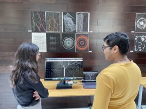
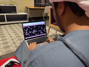
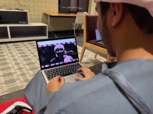
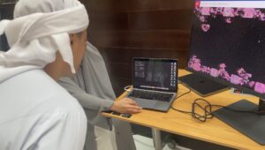
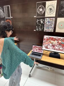
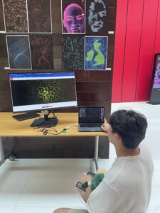
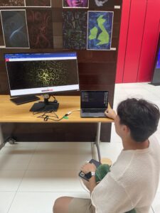
User Interaction Videos from the IM Showcase:

Today’s showcase was a success! It was really rewarding to see people enjoying the interaction and appreciating my work.

Here are a few videos:

IMG_2671 IMG_2673

As well as photos:

Future Improvements:

For the future, I’d like to code multiple fractal trees so that it’ll be like a forest of fractal trees altogether forming a landscape of its own.

Another feature I’d like to try out is associating different audio files depending on the backdrop so that the audio fits the time period or the atmosphere of the image better; for example, for my modern landscape, I’d like to add K-pop tracks or more modern instruments such as guitar, piano, etc.

Overall, I felt like I could really showcase all the lessons and skills I’ve learned during this class this semester into this final project, and I’m very satisfied with my work!

Final Project – Sidrat al Muntaha

Idea

Sidrat Al-Muntaha | artnexploration

Sidrat al-Muntaha (Lote Tree) is the farthest boundary in the seventh heaven which no one can pass. It is called Sidrat al-Muntaha because the knowledge of the angels stops at that point, and no one has gone beyond it except the final prophet and messenger of Allah, Muhammad ﷺ. It is mentioned both in Quran and in Hadith when prophet Muhammad ﷺ was invited by Allah SWT for a visit known as Isra and Mi’raj.

I decided to make my final assignment a personal rendition of this scene, the boundary between heaven and Earth, home to a the colossal tree; Sidrat al-Muntaha.

Process

*********************************************************

  • Open sketches in new tabs for proper code executions
  • After clicking execute will take a few seconds to initiate ml5 library, user will get confirmation message in serial once ready and working.

*********************************************************

Iterations 1

Give the code a few seconds to start going, it takes a while for the ml5 library to come to action. You will get a message printed when it is ready, and you can raise your hand and see it reflected on p5.js.

I brought handposenet into my WEBGL canvas sketch and got it to work well on a small sqaure canvas (eg 500×500). I was able to extract the specific data points I need for the future iterations. The extracted data point is a different color from the others displayed.

I added a point matrix in the center to better understand properties of WEBGL canvas. I did not plan on keeping it to the end, but I am glad I did. It populates the empty canvas without impeding the grand, unsettling, awe atmosphere I am going for.

Iterations 2

In this iterations I worked on  created a 3D fractal tree. I extracted the specific data points I need from the handposenet library and feed it into the branch function. This way we can control the fractal growth of the tree my panning our hand in front of the webcam, horizontally.

Iterations 3

Here I added music and smoothed out tiny changes to make the code more efficient and capable of running on full screen.

Iterations 4

A Maurer rose can be described as a closed route in the polar plane. A walker starts a journey from the origin, (0, 0), and walks along a line to the point (sin(nd), d). These equations are the math behind my portal.

Code Snippets

function drawKeypoints() {
  for (let i = 0; i < predictions.length; i += 1) {
    const prediction = predictions[i];
    for (let j = 0; j < prediction.landmarks.length; j += 1) {
      const keypoint = prediction.landmarks[j];
      fill(0, 255, 0);
      if(i==0 && j==5){
        fill(255, 0, 0);
         }
      noStroke();
      ellipse(keypoint[0], keypoint[1], 10, 10);
    }
    
    handX = predictions[0].landmarks[5][0];
    handY = predictions[0].landmarks[5][1];
  }
}

The code works in conjunction with a machine learning model (PoseNet) that detects and provides information about human poses. The predictions array is assumed to contain information about these poses, and the nested loops iterate through each pose and its keypoints. The ellipses are then drawn on the canvas based on the x and y coordinates of each keypoint, with special handling for a specific keypoint (index 5 of the first pose).

function branch(len){
  strokeWeight(map(len,10,100,1,10));


  let glowColor = color(255, 255, 255); // Set the glow color

   ambientMaterial(glowColor); // Set the ambient material for the glow


  stroke(map(len,10,100,50,255));
  line(0,0,0,0,-len-2,0);
  
  translate(0,-len);
  
  let growth = map(handX,windowWidth-300,0+100,25,10);
  // let growth = 14
  
  if(len>growth){
    for (let i = 0; i<3; i++){
      rotateY(random(100,140));
      push();
      rotateZ(random(20,50));
      branch(len*0.7);
      pop();
      
    }
  }
}

The branch function draws a segment of a branching structure, adjusting stroke weight and color based on the segment’s length. It also includes a recursive branching logic, creating a visually interesting and dynamic branching pattern. The growth of the branches is influenced by the x-coordinate of a variable named handX.

for(let i = 0; i<361; i++){
    //mathematical formula for Maurer Rose
    let k = i*d;
    let r = sin(n*k)*500;
    let x = r*cos(k);
    let y = r*sin(k);
    vertex(x,y);
  }

The purpose of this code is to generate and draw a Maurer Rose, a mathematical pattern based on polar coordinates. The Maurer Rose is characterized by its elegant and symmetrical petal-like shapes.

The loop iterates through angles, and for each angle, it calculates the polar coordinates using a formula. These coordinates are then used to draw the shape.

The dynamic aspects of the pattern are introduced by incrementing the parameters n and d over time. This leads to a continuous change in the appearance of the Maurer Rose, creating an animated effect.

In summary, this code produces a visually interesting and dynamic pattern known as a Maurer Rose using mathematical formulas for polar coordinates. The 3D translation and incrementing parameters contribute to the overall visual appeal and variation in the pattern.

IM SHOW Installation

Challenges

  1. The handposenet started acting finicky in WEBGL when the canvas sizes kept changing. The integration of hand pose detection using ml5.js introduces the challenge of synchronizing the detected coordinates with the 3D canvas. Ensuring accuracy and responsiveness in real-time adds complexity to the overall design.
  2. It was challenging to make objects glow the way I wanted, again I think it is because WEBGL treats those properties very differently.

Future Improvements

  1. Enhancing the accuracy of hand pose detection can be achieved through machine learning model fine-tuning or exploring advanced techniques, ensuring a more precise mapping of user gestures to the visual elements.
  2. Implementing an intuitive user interface could provide users with controls to manipulate parameters dynamically. This could include sliders or buttons to adjust variables such as tree growth, portal dynamics, and point matrix density.
  3. I want to add massive orbs revolving around point matrix to act as heaven and Earth.
  4. I want to make the Maurer Rose portal a 3D model as well, like the fractral tree.
  5. Exploring adaptive audio composition techniques, where the soundtrack evolves based on user interactions and the state of the artwork, would enhance the synergy between the visual and auditory elements.


Final Project – A Trip Down Memory Lane

A Trip Down Memory Lane

Concept and Inspiration:

For my final project I was inspired by an idea I had for a film I made last semester. The film’s idea revolved around the concept of archives and old retrieved footage which immediately sparks the thought of old film strips in my mind. Now that films are, for the most part, recorded on digital cameras, I think the idea of recreating the feel of old running film strips through different forms of art is very interesting. I have not seen this exactly being done by any artist however I have definitely came across several who have experimented with developing film tapes in interesting unconventional ways to observe the possible artistic outcomes. One of these artists was an MFA student at NYUAD whose work, similar to the images below, generated films that had a glitching effect because of the way they were developed. Having his work, as well as my film and these images images in mind, I decided to have my final project be a running film strip that is of the color pink, similar to the theme of my film. I also had the added element of user interactivity to it through creating an effect that allows the user’s image to be reflected through the film strip to create the experience of being part of the memory or the archived footage.


Final Result:

Methodology and Application:

I began by experimenting with different ways through which I could achieve the intended design. I started first with the cellular automata mechanisms applying them to a simple sketch that somewhat generated the feel I was going for. In this sketch I mainly worked on applying the regular game of life rules, with an added element of movement, to attempt to generate the running effect of a film strip.

This was simply done by incrementing the horizontal position of the next alive cell as shown below:

// Move the special cells in the next generation
for (let cell of movingCells) {
  let newX = (cell.x + 1) % cols;
  next[newX][cell.y] = {
    alive: 1,
    color: cell.color
  };
}

This code provided the basis of what I ended up creating however, I initially was not satisfied with the outcome because I felt like it felt somewhat static and did not deliver the idea I was going for. I tried to continue experimenting with cellular automata but I felt stuck so I moved on to work with the physics libraries, and I used the video below as inspiration for what my design would look like exactly:

In this draft I started simply by working on the scrolling effect. This was fairly simple to achieve, I create a function that generated squares that spread across the canvas and have basic physics that allows them to update their position, velocity and acceleration.

// Update scroll speed based on direction
    if (moveDirection !== 0) {
        scrollSpeed = min(scrollSpeed + SCROLL_ACCELERATION, MAX_SCROLL_SPEED);
    } else {
        scrollSpeed = 0;
    }

Moving on from there I worked on the static in the background. I created a class of columns that are basically small rectangles that update their horizontal positions while keeping their vertical positions static, this way they appear as though they’re lines moving across the screen. I also worked on adding forces between the rectangles and between the different columns to accentuate the glitching effect within and between the columns.

    update(speed) {
        this.vel.x = speed;
        this.pos.add(this.vel);
        this.vel.mult(0.95);
        this.pos.y += random(-1, 1);
    }

    edges() {
        if (this.pos.x - this.originalX > width / NUM_COLUMNS) {
            this.pos.x = this.originalX;
            this.pos.y = random(height);
        }
    }

    display() {
        fill(255, this.opacity);
        noStroke();
        rect(this.pos.x, this.pos.y, 1, 10);
    }

    applyForce(force) {
        this.vel.add(force);
    }
}

function applyGlitch(particle) {
    if (random(1) < 0.05) {
        particle.pos.y += random(-10, 10);
        particle.opacity = random(50, 255);
    }
}

To further amplify the design I also created a class of different sized dots that play the role of the grain in the background. From there I worked on having the colors change based on columns’ proximities and I also added sounds to create the nostalgic feel of memories.

I then came across this sketch that generated a pixelated image of the user through webcam input. It basically did so by incrementing the position of the pixel from the webcam input so that it displays in a pixelated manner. I really liked the aesthetic of it and decided to include it in my sketch.

I did so by creating a layer that only appears when the flashing effect occurs. This layer appears as the opacity of the main sketch decreases. Below is the final outcome of what I created.

I did basic user testing and presented this sketch to the class and received two main comments, one that it is too slow and two that there is somewhat of a disconnect between the film strip and the image that appears. Hence I decided to give it another try and experiment once again with what I had created earlier using cellular automata.

I started off by adding the squares to my sketch that used regular game of life rules because I felt like it is what adds the essence of a film strip to the sketch. I then moved on to work on the part I found most challenging in my sketch which is coordinating between the webcam and the cellular automata mechanisms. I looked into several tutorials and learnt different methods from each of them.

From this tutorial I understood the way in which I could translate the pixels inputted from the webcam in order to be able to generate them as pixels based on cellular automata rules. It showed that the indices of the pixels inputted could be read as well as their colors and opacities through the function below which generally reads the red, green, blue, and opacity levels of each pixel inputted.

//Capture the webcam input as pixels
   capture.loadPixels();
   
   // Calculate the scale based on board columns and rows
   let captureScaleX = capture.width / columns;
   let captureScaleY = capture.height / rows;
   
   // Loop through all columns and rows of board
   for (let i = 0; i < columns; i++) 
   {
     for (let j = 0; j < rows; j++) 
     {
       // Then calculate the position corresponding to the cell from the webcam input 
       let x = i * captureScaleX;
       let y = j * captureScaleY;
       
       // Also calculate the index of each pixel in the webcam input to access its brightness and adjust its life
       //Multiplying by 4 because each pixel has 4 color channels to go through
       let webcamPixelIndex = (floor(y) * capture.width + floor(x)) * 4; 
       
       // Calculate the brightness of the webcam input as average of RGB values
       let brightness = (capture.pixels[webcamPixelIndex] + capture.pixels[webcamPixelIndex + 1] + capture.pixels[webcamPixelIndex + 2]) / 3; 

I then applied a general cellular automata rule to have the cells alive or dead based on their brightness. Following that I added other elements that I had included in previous iterations of this project such as the random pink color generating function, the grain in the background, the trail of the squares and the cells, the sounds, the image exporting function, and finally the menu and return button.

The menu I created was quite simple, it used the film strip’s squares to keep the aesthetic continuous, and contained simple instructions to guide the user through using the program. The button was something I hadn’t worked with in this class but it was simple to achieve, I just had to match the mouse coordinates with the position of the button and edit the mouse clicked function.

//.. This function draws the menu with the instructions
function drawMenu() 
{
  background(0);
  fill(0, TRAIL_OPACITY); 
  rect(0, 0, width, height);

  // Draw the squares in the menu
  drawAndUpdateSquares();
  const buttonWidth = 200;
  const buttonHeight = 50;
  const buttonX = (width - buttonWidth) / 2;
  const playButtonY = height / 2 - 65;
  
  .... 

  text('Press the key "e" to export your image', width / 2, height / 4 + 280);
    text('Press the key "b" to return back to the main menu', width / 2, height / 4 + 300);
  
  fill(randomPink());
  rect(buttonX, playButtonY, buttonWidth, buttonHeight, 20);
  fill(255);
  textSize(28);
  text('START', buttonX + 93, playButtonY + 25);
}

Challenges and Aspects I am Proud of: 

In terms of challenges I think the main challenge I faced was in terms of translating the webcam input as mentioned previously, but also understanding the general idea of how cellular automata works was something I had to figure out to be able to generate results that did not seem so static like my initial sketch. I relied on the sketches we did in class for reference as well as a few tutorials like the one below that showed me how I could create my own rules that are based on cellular automata which is what inspired me to have the cells react to brightness and work accordingly.

User Testing: 

Once I had the code working I tested it with some of my friends who really enjoyed exporting their pixelated images and running through the film tape but made a comment on the way the image appears and dies instantly when the mouse is released. Below are some of the images I took while they were testing the project:

Based on my friend’s comment I worked on the part that I think I am most proud of which is the speed at which the images die or disappear. When I first managed to get the effect to work, the cells inputted from the webcam would die as soon as the mouse was released, leaving somewhat of a disconnect between the two effects. This was a simple fix that I feel really transformed the effect and made it a lot nicer and fun to interact with because it allowed the user to view their image as it passed through the film strip and slowly disappeared.

// Determine the life of the cells based on the brightness of webcam input 
        if (brightness > 128) 
        {
        // If pixel is bright cell is alive and lifespan is 15 so it stays on canvas for a while
          board[i][j].alive = 1;
          lifespan[i][j] = 15; 
        } else 
        {
          // If pixel is dark cell is dead
          board[i][j].alive = 0;
        }

Ideas and Further Improvement: 

For future improvements I think I would add more interactivity in terms of color, I want to add more choices for the user to allow them to create their own color pallet and generate their own film strip that is based on how they picture their memories. I think the mouse clicked function could also be switched to a key or something that is easier for the users to interact with to allow them to enjoy their images without having to worry about clicking any buttons. One thing I also think I should work on improving is the general reaction to light and brightness because I found after the show last night that users dressed in lighter clothing had their clothing appear as alive cells and everything else as dead which meant that their faces were barely visible. This was also due to the fact that the area we were presenting in was very well-lit which meant that the camera detected other brighter objects from the background. With that said, I think the project was fun to work on and generally interact with.

Images from IM Show: 

Final Project – Consciousness Canvas by Abdelrahman Mallasi

Concept

In my final project, I delve into the mysterious realm of hypnagogic and hypnopompic hallucinations – vivid, dream-like experiences that occur during the transition between wakefulness and sleep. These phenomena, emerging spontaneously from the brain without external stimuli, have long fascinated me. They raise profound questions about the brain’s capacity to generate alternate states of consciousness filled with surreal visuals.

My interest in these hallucinations, particularly their elusive nature and the lack of complete understanding about their causes, inspired me to create an interactive art piece.I chose this topic due to my fascination with these mind-states and the capacity of our brains to generate alternate states of consciousness with surreal visuals and experiences. I drew inspiration from Casey REAS, an artist known for his generative artworks. Below is some examples of his work named “Untitled Film Stills, Series 5“, showcasing facial distortions and dream-like states.

.

Experts are still exploring what exactly triggers these hallucinations. As noted by the Sleep Foundation, “Visual hypnagogic hallucinations often involve moving shapes, colors, and images, similar to looking into a kaleidoscope,” an effect I aimed to replicate with the dynamic movement of boids in my project. In addition, auditory hallucinations, as mentioned by VeryWellHealth, typically involve background noises, which I have tried to represent through the integration of sound corresponding to each intensity level in the project.

In conceptualizing and creating this project, I embraced certain qualities that may not conventionally align with typical aesthetic standards. The final outcome of the project might not appear as the most visually appealing or aesthetically organized work. However, this mirrors the inherent nature of hallucinations – they are often messy, unorganized, and disconnected. Hallucinations, especially those experienced at the edges of sleep, can be chaotic and disjointed, reflecting a mind that is transitioning between states of consciousness.

Images and User Testing


IM Showcase Documentation


Implementation Details and Code Snippets

At the onset, users are prompted to choose an intensity level, which dictates the pace and density of the visual elements that follow. Once the webcam is activated using ml5.js, the program isolates the user’s face, creating a distinct square around it. This face area is then subjected to pixel manipulation, achieving a melting effect that symbolizes the distortion characteristic of hallucinations.

Key features of the implementation include:

  • Face Detection with ml5.js: Utilizing ml5.js’s FaceAPI, the sketch identifies the user’s face in real-time through the webcam.
       faceapi = ml5.faceApi(video, options, modelReady); // initializes the Faceapi with the video element, options, and a callback function modelReady
      
      function modelReady() {
    
        faceapi.detect(gotFaces); //starts the face detection process
    }
    
    function gotFaces(error, results) {
        if (error) {
            console.error(error);
            return;
        }
        detections = results; // stores the face detection results in the detections variable
        faceapi.detect(gotFaces); // ensures continuous detection by recursion
    }
  • Distortion Effect:
    • Pixelation Effect: The region of the user’s face, identified by the face detection coordinates, undergoes a pixelation process. Here, I average the colors of pixels within small blocks (about 10×10 pixels each) and then recolor these blocks with the average color. This technique results in a pixelated appearance, making the facial features more abstract.
    • Melting Effect: To enhance the hallucinatory experience, I applied a melting effect to the pixels within the face area. This effect is achieved by shifting pixels downwards at varying speeds. I use Perlin noise to help create an organic, fluid motion, making the distortion seem natural and less uniform.
      // in draw function
      
      // captures the area of the face detected by the ml5.js faceapi       
      image(video.get(_x, _y, _width, _height), _x, _y, _width, _height);
      
      // apply pixelation and melting effects within the face area
              let face = get(_x, _y, _width, _height);
      
              face.loadPixels();
      
      // for pixelation effect, this goes through the pixels of the isolated face area 
      // creates pixelated effect by averaging colors in blocks of pixels
              for (let y = 0; y < face.height; y += 100) {
                  for (let x = 0; x < face.width; x += 100) {
                      let i = (x + y * face.width) * 4;
                      let r = face.pixels[i + 0];
                      let g = face.pixels[i + 1];
                      let b = face.pixels[i + 2];
                      fill(r, g, b);
                      noStroke();     
                  }
              }
      
      // for melting effecr, this shifts horizontal lines of pixels by an offset determined by Perlin noise
        for (let y = 0; y < face.height; y++) {
          let offset = floor(noise(y * 0.1, millis() * 0.005) * 50);
                  copy(face, 0, y, face.width, 1, _x + offset, _y + y, face.width, 1);
              }
  • Boid and Flock Classes: The core of the dynamic flocking system lies in the creation and management of boid objects. Each boid is an autonomous agent which exhibits behaviors like separation, alignment, and cohesion.
    In selecting the shape and movement of the boids, I chose a triangular form pointing in the direction of their movement. This design choice was done to evoke the unsettling feeling of a worm infestation, contributing to the overall creepy and surreal atmosphere of the project.

    show(col) {
    
            let angle = this.velocity.heading(); // to point in direction of motion
            fill(col);
            stroke(0);
            push();
            translate(this.position.x, this.position.y);
            rotate(angle);
           
    
                beginShape(); // to draw triangle
                vertex(this.r * 2, 0);
                vertex(-this.r * 2, -this.r);
                vertex(-this.r * 2, this.r);
                endShape(CLOSE);
            
            pop();
        }
    
  • Intensity Levels: By adjusting parameters like velocity, force magnitudes, and number of boids created, I varied the dynamics and sound suitable for each intensity level of the hallucination simulation. the below code shows the Medium settings for instance.
     let btnMed = createButton('Medium');
        btnMed.mousePressed(() => {
            maxBoids=150; // change numbe rof boids
    //ensures user selects only one level at a time
           btnLow.remove();
           btnMed.remove();
           btnHigh.remove();
          initializeFlock(); // starts the flock system only after the user selects a level
          soundMedium.loop(); // plays sound
        });
    // in boids class
    // done for each intensity  
    
     behaviorIntensity() {
    
          if (maxBoids === 150) { // Medium intensity
                this.maxspeed = 3;
                this.maxforce = 0.04;
                this.perceptionRadius = 75;
        }
    
  • Tracing: the boids, as a well as the user’s distorted face,  leave a trace behind them as they move. This creates a haunting visual effect which contributes to the disturbing nature of the hallucinations. This effect is achieved by not including a traditional background function in the sketch. This design choice ensures that previous frame’s drawings are not cleared, allowing for a persistent visual trail that adds to the hallucinatory quality of the piece. I experimented with alternative methods to create a trailing effect, but found that slight, fading trails did not deliver the intense, lingering impact I sought. The decision to forego a full webcam feed was crucial in preserving this effect.
  • Integrating Sound: for each intensity level, I integrated different auditory effects. These sounds play a crucial role in immersing the user in the experience, with each intensity level featuring a sound that complements the visual elements.
  • User Interactivity: the user’s position relative to the screen – left or right – changes the color of the boids, directly involving the user in the creation process. The intensity level selection further personalizes the experience, representing the varying nature of hallucinations among individuals.
    if (_x + _width / 2 < width / 2) { // Face on the left half
               flockColor = color(255, 0, 0); // Red flock
           } else { // Face on the right half
               flockColor = color(100,100,100); // Black flock
           }
    
           // Run flock with determined color
           flock.run(flockColor);

    The embedded sketch doesn’t work here but here’s a link to the sketch.

    Challenges Faced

    • Integrating ml5.js for Face Detection: I initially faced numerous errors in implementing face detection using the ml5.js library.
    • Pixel Manipulation for Facial Distortion: Having no prior background in pixel manipulation, this aspect of the project was both challenging and fun.
    • Optimization Issues:
    • In earlier iterations, I aimed to allow users to control the colors and shapes of the boids. However, this significantly impacted the sketch’s performance, resulting in a heavy lag.I tried various approaches to mitigate this:
      • Reducing Color Options: Initially, I reduced the range of colors available for selection, hoping that fewer options would ease the load. The sketch was still not performing optimally.
      • Limiting User Control: I then experimented with allowing users to choose either the color or the shape of the boids, but not both. However, this didn’t help either.
      • Decreasing the Number of Boids:  I also experimented with reducing the number of boids. However, this approach had a downside; fewer boids meant less dynamic and complex flocking behavior. The interaction between boids influences their movement, and reducing their numbers took away from the visuals.
    •  I then decided to shift the focus from user-controlled aesthetics to user-selected intensity levels. This change allowed for a dynamic and engaging experience without lagging.

Aspects I’m Proud Of

  • Successfully integrating ml5’s face detection elements
  • Being able to distort the face by manipulating pixels
  • Being able to change the colors of the boids by the user’s position on the screen
  • Introducing interactivity by creating buttons that customize the user’s experience
  • Remaining flexible and thinking of other alternative solutions when running into issues.

Future Improvements

Looking ahead, I aim to revisit the idea of user-selected colors and shapes for the boids. I believe that with further optimization and refinement, this feature could greatly enhance the interactivity and visual appeal of the project, making it an even more immersive experience.

I also plan to add a starter screen which will provide users with an introduction to the project, offering instructions and a description of what to expect. This would make the project more user-friendly. Due to time constraints, this feature couldn’t be included.

References

Hypnagogic Hallucinations: Unveiling the Mystery of Waking Dreams


https://www.verywellhealth.com/what-causes-sleep-related-hallucinations-3014744


Final Project: Kinetic Personalities

Concept

My project serves as a metaphor for the ever-changing nature of human identity and the many facets that constitute an individual. Inspired by the dynamic principles of cellular automata, the project visualizes a grid of cells that continuously transition between phases of life and dormancy, mirroring the fluidity of human existence. Each cell represents a different element of one’s personality, similar to the various roles, hobbies, and experiences that define a person at a certain point in time. The periodic interplay of dying and born cells encapsulates the core of personal development and adaptability over time.

Video Demonstration

Images

Interaction Design

I crafted the interaction design to be both intuitive and playful, encouraging whole-body engagement. A key goal was to instill an element of discoverability and surprise within the user experience. For instance, the skeleton dynamically lights up when wrists are drawn near, while the color palette transforms as the wrists move apart. This intentional design seeks to not only captivate users but also symbolize a broader narrative—the idea that individuals possess the inherent power to shape and sculpt their own personalities, paralleling the dynamic changes observed in the visual representation. More about the interaction design was discovered during the user testing, described below.

User Testing

User Testing was a crucial stage in the development of my project. Observing and hearing people’s expectations and frustrations while using my project helped to see the goals of my project more clearly.

For instance, at first I was thinking not to include a human skeleton figure mimicking the participant, and I was considering the option of a black and white video display. Participants were more fond of the video as it allowed them to get visual feedback of their pose and how their actions are perceived by the camera. Since video display was a little too distracting for the eye, but visual feedback of participant’s pose was desired, my solution was including an abstract skeleton figure by taking advantage of the ml5.js library.

An additional valuable observation emerged in relation to event design. Initially, I had one event set the event trigger to activate cells within the skeleton when wrists came close. While contemplating potential actions for triggering another event, a participant proposed that an intuitive approachwould be activating the second event when hands were stretched apart. Taking this insightful suggestion into account, I subsequently integrated the color change mechanism to occur when the distance between wrists was wide.

Here is a video of the final user testing:

Code Design

The code utilizes of the p5.js and ml5.js libraries to create a cellular automata simulation that reacts to a user’s body movements filmed via a webcam. The ml5 PoseNet model gathers skeletal data from the video feed of the user and identifies major body parts. The activation of cells in a grid is influenced by the positions of the wrists. The grid symbolizes a cellular automata, in which cells evolve according to predefined rules. The user’s wrist movements activate and deactivate cells, resulting in complicated patterns. The project entails real-time translation, scaling, and updating of the cellular automata state, resulting in an interactive and visually pleasant experience that combines cellular automata, body movement, and visual aesthetics.

One of the key parts regarding code was correctly calculating the indices of the cells that need to be activated based on the video ratio. I decided that a 9×9 grid gave the best visual result, here is my code for the activation of cells on the left wrist:

let leftWristGridX = floor(
      ((pose.leftWrist.x / video.width) * videoWidth) / w
    );
    let leftWristGridY = floor(
      ((pose.leftWrist.y / video.height) * videoHeight) / w
    );

    // Activate cells in a 9x9 grid around the left wrist
    for (let i = -4; i <= 4; i++) {
      for (let j = -4; j <= 4; j++) {
        let xIndex = leftWristGridX + i;
        let yIndex = leftWristGridY + j;

        // Check if the indices are within bounds
        if (xIndex >= 0 && xIndex < columns && yIndex >= 0 && yIndex < rows) {
          // Set the state of the cell to 1 (activated)
          board[xIndex][yIndex].state = 1;
        }
      }
    }

Another key part was the events. Here is the code for the color switch event:

// Creating an event to change colors
    let wristsOpen =
      dist(leftWristGridX, leftWristGridY, rightWristGridX, rightWristGridY) >
        60 &&
      dist(leftWristGridX, leftWristGridY, rightWristGridX, rightWristGridY) <
        80;

    if (wristsOpen) {
      // Activate the event for all existing cells
      for (let i = 0; i < columns; i++) {
        for (let j = 0; j < rows; j++) {
          board[i][j].event = true; // responsible for coloir change in Cell class
        }
      }
    } else {
      // Deactivate the event for all existing cells
      for (let i = 0; i < columns; i++) {
        for (let j = 0; j < rows; j++) {
          board[i][j].event = false;
        }
      }
    }

Nevertheless, probably the biggest challenge was the accurate full-screen display. I utilized additional functions to handle that, which required to re-initialize the board once the dimensions of the screen changed.

Another important function was deactivateEdgeCells() functions. For some reason (probably because of a different number of neighbors), the edge cells would not deactivate as the rest of the cells once a wrist crossed them. Therefore, I used an additional function to handle the issue that loops through the edge cells and sets their state to 0 if they were activated:

function deactivateEdgeCells() {
  for (let i = 0; i < columns; i++) {
    for (let j = 0; j < rows; j++) {
      // Check if the cell is at the edge and active
      if (
        (i === 0 || i === columns - 1 || j === 0 || j === rows - 1) &&
        board[i][j].state === 1
      ) {
        board[i][j].state = 0; // Deactivate the edge cell
      }
    }
  }
}
Sketch

Future Improvements

Here is a list of possible further implementations:

  • Music Integration: The addition of music could enhance the overall experience, encouraging more movement and adding a playful dimension to the interaction.
  • Dance: Exploring the combination of the sketch with a live dance performance could result in a unique and captivating synergy of visual and kinesthetic arts.
  • Multi-User Collaboration: Sketch is currently supporting interaction for one person. Expanding the sketch to accommodate multiple users simultaneously would amplify the playfulness and enrich the collaborative aspect of the experience.
  • Additional Events: one event that I would have loved to explore further was the change in CA rules that generated a beautiful pattern expanding through the whole canvas. I believe it would make the sketch more dynamic.
  • Events on more advanced poses: Involving the legs or the head movements could make the project more intricate and add to the discoverability and surprise aspects.
Resources

A key element was the use of the ml5.js library, for the implementation of which I was relying on Daniel Shiffman’s tutorials.

The CA rules were a happy accident which I discovered when I was experimenting in my CA weekly assignment.

IM Show Documentation

Final Project: Many Worlds

Concept

At the heart of my final project lies an ambitious vision: to visually explore and simulate the fascinating theories of multiverses and timelines in physics. This journey, powered by p5.js, delves into the realm where science meets art, imagining our universe as merely one among an infinite array of possibilities. The project captures the essence of the multiverse theory, the many-worlds interpretation, timeline theory, and the intriguing butterfly effect, presenting a dynamic canvas where every minor decision leads to significant, visible changes.

Images

User Testing

Implementation

Description of Interaction Design

Initial User Engagement: Upon launching the simulator, users are greeted with an informative popup window. This window sets the stage for their cosmic journey, outlining their role in crafting universes and navigating timelines. It provides clear instructions on how to interact with the simulation, ensuring users feel comfortable and engaged from the outset.

Canvas Interaction:

  • Creating Timelines: The primary interaction on the canvas is through mouse clicks. Each click places a gravitational point, the inception of a new timeline. This action leads to the emergence of diverging lines, symbolizing the branching of timelines in the multiverse.
  • Timeline Dynamics: The lines stemming from each point spread across the canvas, intertwining to form a complex network of timelines. This visualization represents the ever-evolving nature of the universe, with each line’s path shaped by random divergence, creating a unique multiverse experience.
  • Dimensional Shifts: The use of arrow keys allows users to shift dimensions. Pressing the ‘Up’ arrow key transforms the lines into particle-like forms with a whiter hue, representing the dual nature of light as both particle and wave. This shift is a metaphor for viewing the cosmos from a different dimensional perspective. Conversely, the ‘Down’ arrow key reverts these particles into their original line state, symbolizing a return to the initial dimension.

Customization and Control:

  • Radius and Decay Parameters: Users can adjust the radius of the gravitational points and the decay rate of the timelines. These parameters influence the behavior of the timeline strings, allowing for a more personalized and interactive experience.
  • Interactive Buttons:
    • Clear Button: Resets the canvas, clearing all timelines and providing a fresh start.
    • Random Button: Randomizes the radius and decay parameters, introducing an element of unpredictability.
    • Update Button: Applies changes made to the radius and decay settings, updating the canvas accordingly.
  • Precise Editing: By holding the shift key and clicking, users can erase specific parts of the timelines, allowing for detailed adjustments and creative control.

This design not only immerses users in the concept of multiverses but also offers an intuitive and engaging way to visualize complex physics theories. Through simple yet powerful interactions, the Multiverse Simulator becomes a canvas where science, art, and imagination converge.

Technical implementation side

Key Steps in Particle Simulation:

  1. Sense: Each particle senses its environment in a unique way, employing three sensors to detect the surroundings based on its heading direction.
  2. Rotate: The particle’s rotation is determined by the sensor readings, allowing it to navigate through the canvas in a realistic manner.
  3. Move: After determining its direction, the particle moves forward, creating a path on the canvas.
  4. Deposit: As particles move, they leave a trace in the form of yellow pixels, marking their journey.
  5. Diffuse: The trail left by each particle expands to the neighboring cells, creating a more extensive network of lines.
  6. Decay: The brightness of each pixel gradually fades, simulating the decay effect over time.

Code Snippets

The core functionality of the project is encapsulated in several key functions:

  • Particle Sensing and Movement:
function sense() {
  // The sense function is responsible for the decision-making process of each particle.
  // - It uses three sensors (left, center, right) to detect the environment ahead of the particle.
  // - Based on the sensor readings, the particle decides whether to continue straight, turn left, or turn right.
  // - This decision influences the particle's path, creating intricate patterns on the canvas as particles avoid their own trails.
  for (let i = 0; i < particles.length; i++) {
    let options = [0, 0, 0];
    options[1] =
      attracters[
        modifiedRound(particles[i][0] + SO * cos(particles[i][2]), "x")
      ][modifiedRound(particles[i][1] + SO * sin(particles[i][2]), "y")];
    options[0] =
      attracters[
        modifiedRound(particles[i][0] + SO * cos(particles[i][2] + SA), "x")
      ][modifiedRound(particles[i][1] + SO * sin(particles[i][2] + SA), "y")];
    options[2] =
      attracters[
        modifiedRound(particles[i][0] + SO * cos(particles[i][2] - SA), "x")
      ][modifiedRound(particles[i][1] + SO * sin(particles[i][2] - SA), "y")];
    if (options[1] >= options[2] && options[1] >= options[0]) {
      continue;
    } else if (options[0] > options[2]) {
      particles[i][2] = (particles[i][2] + RA) % TWO_PI;
    } else if (options[0] < options[2]) {
      particles[i][2] = (particles[i][2] - RA) % TWO_PI;
    } else {
      let rand = Math.random();
      if (rand < 0.5) {
        particles[i][2] = (particles[i][2] + RA) % TWO_PI;
      } else {
        particles[i][2] = (particles[i][2] - RA) % TWO_PI;
      }
    }
  }
}
  • Canvas Interaction:

    function canvasClick() {
      // This function handles user interactions with the canvas.
      // - If the SHIFT key is held down while clicking, it removes particles within the click radius.
      // - If the ENTER key is held, it adds a new emitter at the mouse location.
      // - Otherwise, it spawns new particles around the click location within the specified radius.
      // Each particle is initialized with a random direction.
      if (keyIsDown(SHIFT)) {
        const notRemoved = [];
        for (let xs of particles) {
          if (
            Math.sqrt((mouseX - xs[0]) ** 2 + (mouseY - xs[1]) ** 2) > clickRadius
          ) {
            notRemoved.push(xs);
          }
        }
        particles = notRemoved;
      } else if (keyIsDown(ENTER)) {
        emitters.push([mouseX, mouseY]);
      } else {
        for (
          let i = 0;
          i < particlesPerClick && particles.length < maxParticles;
          i++
        ) {
          let dis = clickRadius * Math.random();
          let ang = TWO_PI * Math.random();
          let x = mouseX + dis * cos(ang);
          let y = mouseY + dis * sin(ang);
    
          particles.push([x, y, TWO_PI * Math.random()]);
        }
      }
    }
  • Decay:

    function decay() {
      // This function manages the decay and diffusion of particle trails.
      // It updates the visual representation of each particle's trail on the canvas.
      // - First, it iterates over the canvas, applying the decay factor to reduce the brightness of trails.
      // - Then, it applies a blur filter (simulating diffusion) to create a smoother visual effect.
      // - Finally, the attracters array is updated based on the decayed and diffused pixel values.
      for (let i = 0; i < imageWidth; i++) {
        for (let j = 0; j < imageHeight; j++) {
          writePixel(at, i, j, attracters[i][j]);
        }
      }
      at.filter(BLUR, diffK);
      for (let i = 0; i < imageWidth; i++) {
        for (let j = 0; j < imageHeight; j++) {
          attracters[i][j] = at.pixels[(i + j * imageWidth) * 4] * decayT;
        }
      }
      at.updatePixels();
    }

    Aspects of the Project I’m Particularly Proud Of

    Reflecting on the development of the Multiverse Simulator, there are several aspects of this project that fill me with a sense of pride and accomplishment:

    1. Complex Algorithm Implementation: The heart of this project lies in its complex algorithms which simulate the behavior of particles in a multiverse environment. Successfully implementing and fine-tuning these algorithms — particularly the sensing, rotating, moving, depositing, diffusing, and decaying behaviors of particles — was both challenging and rewarding. The intricacy of these algorithms and how they bring to life the concept of timelines and multiverses is something I am exceptionally proud of.
    2. Interactive User Experience: Designing an interactive canvas where users can directly influence the creation and evolution of timelines was a significant achievement. The fact that users can engage with the simulation, spawning and altering timelines through intuitive mouse interactions, adds a dynamic layer to the project. This level of interactivity, where each user’s actions uniquely shape the cosmos they’re exploring, is particularly gratifying.
    3. Visual Aesthetics and Representation: The visual output of the simulation is another aspect I take great pride in. The way the particles move, interact, and leave trails on the canvas has resulted in a visually captivating experience. The transition between states — from lines to particles and back, depending on user interaction — not only serves as an artistic representation of the multiverse concept but also adds a profound depth to the visual experience.
    4. Optimizing Performance: Tackling the computational challenges and optimizing the simulation to run smoothly was a significant hurdle. Achieving a balance between the visual complexity and maintaining performance, especially when dealing with thousands of particles and their interactions, was a rewarding challenge. The fact that the simulator runs efficiently without compromising on the intricacies of its visual representations is a testament to the effectiveness of the optimization strategies employed.
    5. Educational Value: The project is not just an artistic endeavor; it’s also an educational tool that visually demonstrates complex physics theories in an accessible and engaging way. Bridging the gap between complex scientific concepts and interactive visual art to create a learning experience is an achievement that adds a lot of value to this project.

Links to Resources Used

In the journey of creating the Multiverse Simulator, various resources played a crucial role in guiding the development process, providing technical knowledge, and inspiring creativity. Here’s a list of some key resources that were instrumental in the project:

  1. Particle System Tutorials:
    • The Nature of Code by Daniel Shiffman: This book and its accompanying videos offer an in-depth look at simulating natural systems using computational models, with a focus on particle systems that was particularly relevant to this project.
  2. Physics and Multiverse Theory:
    • Multiverse Theory Overview: An academic article providing a detailed explanation of the multiverse theory, which helped in ensuring the scientific accuracy of the simulation.
    • Introduction to Quantum Mechanics: Articles and resources that offer a beginner-friendly introduction to quantum mechanics, aiding in conceptualizing the project’s scientific foundation.
  3. Coding Forums and Communities:
    • Stack Overflow: A vital resource for troubleshooting coding issues and learning from the experiences and solutions shared by the coding community.
    • Reddit – r/p5js: A subreddit dedicated to p5.js where developers and enthusiasts share their projects, tips, and ask questions.
  4. Performance Optimization:
    • Web Performance Optimization: Guidelines and best practices from Google Developers on optimizing web applications, which were crucial in enhancing the simulator’s performance.
  5. Software Development Best Practices:
    • Clean Code by Robert C. Martin: A book that offers principles and best practices in software development, guiding the structuring and commenting of the code for this project.

Demo

Full source code

Challenges Faced and How They Were Overcome

The development of the Multiverse Simulator presented several challenges, each demanding creative solutions and persistent effort. Here’s a look at some of the key hurdles encountered and the strategies employed to overcome them:

  1. Complex Algorithm Integration:
    • Challenge: Implementing the complex algorithms that simulate particle behaviors and interactions was a daunting task. Ensuring these algorithms worked in harmony to produce the desired visual effect required a deep understanding of both programming and physics.
    • Solution: To address this, I spent considerable time researching particle systems and physics theories. Resources like “The Nature of Code” were instrumental in gaining the necessary knowledge. Additionally, iterative testing and debugging helped refine these algorithms, ensuring they functioned as intended.
  2. Performance Optimization:
    • Challenge: The simulator’s initial iterations struggled with performance issues, particularly when handling a large number of particles. This was a significant concern, as it impacted the user experience.
    • Solution: Performance optimization was tackled through several approaches. Code was profiled and refactored for efficiency, unnecessary computations were minimized, and the rendering process was optimized. Learning from online resources about efficient canvas rendering and adopting best practices in JavaScript helped immensely in enhancing performance.
  3. User Interface and Experience:
    • Challenge: Creating an intuitive and user-friendly interface that could accommodate the complex functionalities of the simulator was challenging. It was essential that users could easily interact with the simulation without feeling overwhelmed.
    • Solution: The design of the user interface was iteratively improved based on user feedback and best practices in UI/UX design. Simplicity was key; the interface was designed to be minimal yet functional, ensuring that users could easily understand and use the various features of the simulator.
  4. Balancing Artistic Vision with Technical Feasibility:
    • Challenge: One of the biggest challenges was aligning the artistic vision of the project with technical constraints. Translating complex multiverse theories into a visually appealing and scientifically accurate simulation required a delicate balance.
    • Solution: This was achieved by continuously experimenting with different visual representations and consulting resources on generative art. Collaboration with peers and seeking feedback from artistic communities also provided fresh perspectives that helped in making the simulation both aesthetically pleasing and conceptually sound.
  5. Debugging and Quality Assurance:
    • Challenge: Given the complexity of the simulation, debugging was a time-consuming process. Ensuring the quality and reliability of the simulation across different platforms and devices was critical.
    • Solution: Rigorous testing was conducted, including unit testing for individual components and integrated testing for the overall system. Community forums like Stack Overflow were invaluable for resolving specific issues. Cross-platform testing ensured the simulator’s consistent performance across various devices.

Future Improvement Opportunities

Reflecting on the Multiverse Simulator’s journey, there are several areas where the project can be further developed and enhanced. Future improvements will focus on expanding its capabilities, refining user experience, and exploring new technological frontiers:

  1. Advanced User Interactions:
    • Enhancement: Introducing more sophisticated interaction methods, such as gesture recognition or touch-based inputs, could provide a more immersive experience. Integrating virtual or augmented reality elements could also take user engagement to a whole new level.
    • Implementation: Researching emerging technologies in AR/VR and experimenting with libraries that support these features could be the next steps in this direction.
  2. Richer Visual Effects:
    • Enhancement: Enhancing the visual aspects of the simulator with more detailed and diverse effects could make the experience even more captivating. Implementing additional visual representations of quantum phenomena could deepen the scientific authenticity of the project.
    • Implementation: Experimenting with advanced graphics techniques and shaders could provide a wider range of visual outputs, adding depth and variety to the simulation.
  3. Scalability and Performance:
    • Enhancement: Further optimizing the simulation for scalability to handle an even larger number of particles without performance loss would be beneficial. This could allow for more complex simulations and a richer visual experience.
    • Implementation: Leveraging web workers and exploring parallel processing techniques could improve performance. Profiling and optimizing current code to reduce computational overhead can also be continued.
  4. Educational Integration:
    • Enhancement: Developing an educational module that explains the underlying scientific concepts in an interactive manner could transform the simulator into a powerful learning tool.
    • Implementation: Collaborating with educators and scientists to create informative content and interactive lessons could help in integrating this feature.
  5. Community and Collaboration:
    • Enhancement: Building a community platform where users can share their creations, exchange ideas, and collaborate on simulations could foster a more engaged user base.
    • Implementation: Implementing social sharing features and community forums, along with user accounts for saving and sharing simulations, could help build this community.
  6. Accessibility and Inclusivity:
    • Enhancement: Ensuring the simulator is accessible to a diverse audience, including those with disabilities, can make the experience more inclusive.
    • Implementation: Adhering to web accessibility standards, incorporating features like screen reader compatibility, and providing different interaction modes for users with different needs are crucial steps.
  7. Feedback and Iterative Improvement:
    • Enhancement: Regularly collecting user feedback and iteratively improving the simulator based on this feedback can ensure that it continues to meet and exceed user expectations.
    • Implementation: Setting up feedback mechanisms, conducting user testing sessions, and regularly updating the simulator with improvements and new features.

IM Show

Xiaozao Wang – Final Project

Project Title: Morphing the Nature

Source code: https://github.com/XiaozaoWang/DNFinal

Video trailer:

A. Concept:

Similar patterns have been found in animal bodies, plants, and even landscapes. This shows us that maybe things in nature share the same basic algorithm to form their body, including the humans. However, with the development of technology, we think that we have control over other beings and nature, and begin to forget that nature’s wisdom is inherent in our own bodies all the time.

I want to visually explore patterns found in nature and overlay them to the viewer’s figure in the computer through their webcam. Through this project, I aim to promote awareness of our interconnectedness with nature and other living beings. While humans have developed great abilities, we remain part of the natural world that we evolved from. We should respect and learn from nature rather than try to exploit it.

B. Design and Implementation

My project consists of two main parts: 

  1. Generating the patterns based on the mathematical principle behind them.
  2. Capturing the user’s figure using the camera and morphing the patterns onto the figure.

I used Turing’s Reaction-Diffusion Model as the blueprint for generating the patterns. That’s because this model shows how different patterns in nature, from stripes to spots, can arise naturally from a homogeneous state. It is based on the interplay between two kinds of chemicals: the Activator and the Inhibitor, where the activator is trying to reproduce and the inhibitor is stopping it from doing so. Different generating and dying rates of these chemicals create a variety of interesting behaviors that explain the mystery of animal/plant patterns.

I mainly referred to Karl Sims’s version of the reaction-diffusion equation. He has a wonderful research and web art project about Turing’s pattern. https://www.karlsims.com/rd.html

I also learned about ways to translate this equation into code from the coding train: https://youtu.be/BV9ny785UNc?si=aoU4__mLw6Pze6ir

grid[y][x].a = a +
        ((dA * laplaceA(x, y)) -
        (a * b * b) +
        (feed * (1 - a))) * 1;
      grid[y][x].b = b +
        ((dB * laplaceB(x, y)) +
        (a * b * b) -
        ((k + feed) * b)) * 1;

I created a class that stores the concentration of Chemicals A and B of every pixel in the 2D array.

One of the interesting parts is that the “diffusion” part works similarly to the Game of Life. In every update, the new concentration of the center pixel of a 3×3 convolution is calculated based on the concentration of its 8 neighbors, each with a different weight. This causes the chemicals to diffuse into areas around them. In our case, the weights are as follows.

There are results like this:

However, one thing is that the complicated calculations slow down the running of the sketches, and making the canvas bigger also results in lagging. After testing, I found that the p5js library is causing the problem (because it’s a rather large library).

As you can see, even the difference between using the p5 file and the p5.min file can cause such a huge difference in running efficiency: (They both start from the same seed. The one on the right is using p5.min, and runs twice as fast as the one on the left)

Therefore, I decided to use Processing as the platform to develop my project. It is a local software therefore doesn’t have to fetch the library from the web.

Moreover, I reduced the resolution of the canvas by utilizing 2D arrays. (In the webcam part, I also reduced the resolution by storing the information of only the top-left pixel out of an 8×8 pixel grid). By doing this, I was able to expand the canvas size.

Then it comes to the next step: Capturing the user’s figure with the webcam and projecting the patterns on the figure.

This is the logic of implementation:

Firstly, we will need to capture an empty background without any humans, and store the color data in a 2d array. Then we will compare the real-time video captured by the webcam with that empty background, and identify the areas that have large color differences. ( I used the Euclidean distance) These areas will represent where the figure is. And then, we use this precessed layer as a map that controls which part of the pattern layer is shown to the user. Then, we will be able to see that the patterns are only growing on the user’s figure but not on the background!

I added some customizable values to make the project more flexible to different lighting, skin colors, and preferences. As a user, you can move your mouse across the X-axis to change the exposure, and across the Y-axis to change the transparency of the mask.

At last, I added a GUI using the controlP5 library. The user will be able to use the preset patterns and color palettes as well as adjust the parameters on their own.

User testing on IM show:

C. Future Development

  1. I would like to add a color picker to the control panel and allow users to select the color on their own. It is doable with controlP5.
  2. To increase performance, the resolution is sacrificed. I wonder if building a more powerful and fast simulation engine is possible?
  3. I think it would be very interesting to map the patterns to a 3d character in game engines like Unity. As long as we have an understanding of how the equation works, it can be applied to many project forms!

Final Project – Wildfire

Concept:

In order to define fire suppression tactics and design fire risk management policies, it is important to simulate the propagation of wildfires. In my final project, I’ll be using cellular automata to model the spread of wind-driven fire across a grid-based terrain, demonstrating the dynamics of wildfires and exploring different scenarios and factors affecting their spread.

Users will be able to set the initial conditions (i.e. density of vegetation, vegetation type, ignition point), adjust parameters (i.e. wind speed, wind direction, temperature), monitor variables (i.e. frames per second, land proportion, water proportion, burned land), pause, and reset the simulation.

Final Sketch:

https://editor.p5js.org/bdr/full/2S_n0X2gV

Code:

https://editor.p5js.org/bdr/sketches/2S_n0X2gV

Initial sketches:

View post on imgur.com

View post on imgur.com

Papers to be used:

https://www.fs.usda.gov/rm/pubs_int/int_rp115.pdf

Code walkthrough:
Terrain generation:

The generateCells() function creates a terrain by dividing the map into cells to form a 2D grid (representing a cellular automata). Within each grid cell (defined by x and y coordinates), various noise functions are used to generate different aspects of the terrain.

generateCells() mainly defines the elevation of each cell in the grid through a combination of noise functions. Noise, Marks, Distortion, Bump, and Roughness are all variables employed with different scaling factors and combinations of input derived from the x and y coordinates. The noise functions were determined through trial and error.

roughness = noise(x / 600, y / 600) - 0.3;
bumpdistort = noise(x / 20, y / 20);
bumpnoise = noise(x / 50, y / 50, 2 * bumpdistort);
h = noise1 + sq(sq(noise2)) + roughness * bumpnoise - 0.8;

The color of each point is determined based on its height and other noise values, influencing factors such as land type (e.g., vegetation or ocean) and terrain features.

Using HSB as the color mode, the hue component represents the color’s tone (e.g., red, green, blue) while the brightness component corresponds to the perceived elevation. This makes it intuitive to represent different elevations using a gradient of colors (e.g., blue for lower elevations to white for higher ones), making the terrain visually more coherent and natural-looking.

if (h > 0) {
  clr = color(20 + 10 * (marks1 - 4) + 10 * (marks2 - 4) + 20 * distort1 + 50 * distort2 + bumpnoise * 15,
  min(100, max(50, 100 - 500 * roughness)), 75 + 65 * h);
  veg = getColor(clr)
  pointData = { x: x, y: y, color: clr, vegetation: veg, fire: 0, elev: elevationClr, temp:null};
  landCnt++;

} else {
  clr = color(160, 100, 185 + max(-45, h * 500) + 65 * h + 75 * (noise2 - 0.75));
  veg = getColor(clr)
  pointData = { x: x, y: y, color: clr, vegetation: veg, fire: 0, elev: elevationClr, temp:null};
  oceanCnt++;
}

The elevation/height is mapped as to the more the cell is in the middle of the ocean, the deeper it gets, and the more in the middle of the land, the higher it gets.

Initial step:

View post on imgur.com

Simplified sketch: As the sketch needed around 3 seconds to render, and cellular automata required a constant update of the sketch, simplifying the sketch was crucial. So, instead of calculating the noise for every pixel, I skip one by predicting its color.

View post on imgur.com

Vegetation:

Vegetation type propagation probability:
– No vegetation: -1
– Cultivated: -0.4
– Forests: 0.4
– Shrub: 0.4

Vegetation density propagation probability:
– No vegetation: -1
– Sparse: -0.3
– Normal: 0
– Dense: 0.3

Rules:

R1: A cell that can’t be burned stays the same
R2: A cell that is burning down at the present time will be completely burned in the next iteration.
R3: A burned cell can’t be burned again.
R4: If a cell is burned, and its neighbors contain vegetation fue, the fire can then propagate with a given probability (factors).

The fire propagation probabilities are:

View post on imgur.com

P0: ignition point (user interaction)
P_veg: vegetation type
P_den: vegetation density
Ps: topography
Pw: wind speed and direction

View post on imgur.com

with C1 and C2 are adjustable coefficients
V is the wind speed
O is the angle between the wind direction and the fire propagation (if aligned, Pw increases)

View post on imgur.com

with a: adjustable coefficient
o: the slope angle of the terrain

View post on imgur.com

with E: elevation of the cell
D: the size of the square cell if adjacent or sqrt(2*cellSize) if diagonal

Cellular Automata rules:

Implement rules governing the spread of fire: Fuel, topography, wind, and humidity.
R1: A cell that can’t be burned stays the same
R2: A cell that is burning down at the present time will be completely burned in the next iteration.
R3: A burned cell can’t be burned again.
R4: If a cell is burned, and its neighbors contain vegetation fue, the fire can then propagate with a given probability (factors).

function generateNextGeneration() {
    for (let i = 0; i < width; i+=2) {
        for (let j = 0; j < height; j+=2) {
            let neighbors = countNeighbors(i, j);
            let windAffectedProb = calculateWindEffect(i, j, windSpeed, windDirection);

            if (grid[i][j].fire==0 && neighbors==0){ // no fire, neighbors no fire
                nextGrid[i][j].fire=0;
            }
            if (grid[i][j].fire==0 && neighbors!=0 && grid[i][j].vegetation==0){ // water, neighbor fire, probability 0%
                nextGrid[i][j].fire=0;
            }
            probability = Math.floor(random(1,100));
            windInfluence = random(0, 100);
            if (grid[i][j].fire==0 && neighbors!=0 && grid[i][j].vegetation==1 && probability<10 && windInfluence < windAffectedProb && temperature>0){ // sparse, neighbor fire, probability 10%
                nextGrid[i][j].fire=1;
                nextGrid[i][j].color=color(14, 252, 113);
            }
            probability = Math.floor(random(1,100));
            windInfluence = random(0, 100);
            if (grid[i][j].fire==0 && neighbors!=0 && grid[i][j].vegetation==2 && probability<50 && windInfluence < windAffectedProb && temperature>0){ // no fire, neighbor fire, normal veg, probability 70%
                nextGrid[i][j].fire=1;
                nextGrid[i][j].color=color(14, 252, 113);
            }
            probability = Math.floor(random(1,100));
            windInfluence = random(0, 100);
            if (grid[i][j].fire==0 && neighbors!=0 && grid[i][j].vegetation==3 && probability<30 && windInfluence < windAffectedProb && temperature>0){ // no fire, neighbor fire, dense veg, probability 100%
                nextGrid[i][j].fire=1;
                nextGrid[i][j].color=color(14, 252, 113);
            }
            else if (grid[i][j].fire==1){ // burning
                nextGrid[i][j].fire==-1;
                nextGrid[i][j].color=color(0, 0, 57);
                burnedCnt++;
                burnedBlocks[`${i}_${j}`] = true;
            }
            else if (grid[i][j].fire==-1){ // burned
                nextGrid[i][j].fire==-1;
                nextGrid[i][j].color=color(0, 0, 57);
            }
        }
    }
    swapGenerations();
}
Other Maps:

Elevation Map: Users are able to visualize the elevation of the terrain by using the button at the right of the screen.

View post on imgur.com


Elevation type: Users are also able to visualize the tyoe of vegetation (forests, shrubs, cultivated…)

View post on imgur.com

Wind: Users are also able to see the wind direction and modify it using the slider.

View post on imgur.com

Challenges:

Improving the computation time was a rather challenging time. After optimizing it, it went from 3s to 0.35s.

IM Show Pictures:

View post on imgur.com

View post on imgur.com