Midterm Progress #2 “Dynamic Hearts” – Stefania Petre

Concept

The Dynamic Hearts project aims to create an engaging visual experience through the generation of heart-shaped forms that interact with each other. This project draws inspiration from the ebb and flow of life, where hearts symbolize love, connection, and emotional depth. The hearts dynamically change in size, color, and motion based on Perlin noise, simulating a dance of souls interacting with one another, occasionally colliding and sometimes drifting apart, creating a mesmerizing display of movement and color.

Design

1. Shapes: The sketch generates multiple heart shapes whose sizes and positions are influenced by Perlin noise, resulting in smooth and organic motions. Each heart is drawn in the center of the canvas, enhancing the visual symmetry and creating a harmonious composition.

2. Color Palette: Colors are assigned dynamically based on the index of each heart, producing a gradient effect across the shapes. This choice evokes a sense of depth, movement, and emotional resonance, as colors shift and blend seamlessly.

3. Interactivity: The motion of the hearts is dictated by a combination of Perlin noise and an orbiting pattern. This feature adds a layer of interactivity, allowing viewers to experience the visual output as a living, breathing entity that shifts with the rhythm of the noise, mimicking the spontaneity of life itself.

States and Variations

The sketch can exhibit different states based on its parameters:
– The number of heart shapes can be adjusted to create a denser or sparser visual.
– Modifying the radius and orbit settings can lead to variations in the hearts’ motions and interactions, resulting in diverse visual patterns.
– The introduction of additional interactive elements, such as changing behavior through keyboard inputs or dynamically adjusting colors based on viewer interactions, can further enrich the visual experience.

Identified Risks

One of the more complex aspects of this project is managing the performance and responsiveness of the visual output, especially with a larger number of hearts. Ensuring the sketch runs smoothly without lag is essential for providing a seamless user experience.

Risk Reduction Strategies

To minimize potential risks:
– The number of heart shapes is set to a manageable level (15) to maintain performance while allowing for a visually rich experience.
– The use of `noFill()` and `strokeWeight()` enhances rendering efficiency while preserving visual quality.
– Performance will be tested across different devices to ensure responsiveness, with adjustments made based on testing results.

Process and Evolution

Starting from my initial concept of creating dynamic spirals, I aimed to design a captivating visual that responded to user input. The initial draft featured spiraling lines that changed in size and color based on mouse position. However, through a process of exploration and experimentation, I was inspired to shift my focus to heart shapes, which felt more resonant with the themes of connection and emotional depth.

The transition from spirals to hearts involved redefining the visual language of the project. I began by adapting the existing code, replacing the spirals with heart shapes that could interact in an engaging manner. By leveraging Perlin noise, I was able to create fluid and organic movements that echoed the unpredictability of human emotions and relationships. The resulting composition features hearts that move like souls, sometimes colliding and other times drifting apart, providing a poignant metaphor for our connections in life.

Final Product

In conclusion, the Dynamic Hearts project represents a culmination of my explorations in interactive art, showcasing how shapes can convey emotional narratives and foster a sense of connection through visual interaction. The final product has evolved significantly from the initial draft, transforming into a rich and engaging experience that reflects the complexity of life and love.


//Dynamic Hearts - Midterm by SP

let numShapes = 15; // Number of shapes
let shapeRadius = 100; // Distance from center
let maxRadius = 1000; // Maximum size for shapes
let angleStep = 0.02; // Speed of rotation

let noiseOffsetX1 = 0; // X-offset for Perlin noise (Group 1)
let noiseOffsetY1 = 1000; // Y-offset for Perlin noise (Group 1)

let noiseOffsetX2 = 5000; // X-offset for Perlin noise (Group 2)
let noiseOffsetY2 = 6000; // Y-offset for Perlin noise (Group 2)

let orbitRadius = 200; // Distance between the two groups

function setup() {
    createCanvas(windowWidth, windowHeight);
    noFill();
    strokeWeight(2);
}

function draw() {
    background(0, 30);

    // Calculate the central orbit angle based on Perlin noise
    let orbitAngle1 = noise(noiseOffsetX1) * TWO_PI; // Group 1 orbit angle
    let orbitAngle2 = noise(noiseOffsetX2) * TWO_PI; // Group 2 orbit angle

    // Group 1 position based on orbit
    let centerX1 = orbitRadius * cos(orbitAngle1);
    let centerY1 = orbitRadius * sin(orbitAngle1);
    
    // Group 2 position based on orbit, opposite direction
    let centerX2 = orbitRadius * cos(orbitAngle2 + PI);
    let centerY2 = orbitRadius * sin(orbitAngle2 + PI);

    // Draw first group of hearts
    push();
    translate(width / 2 + centerX1, height / 2 + centerY1);
    drawShapeGroup(numShapes, noiseOffsetX1, noiseOffsetY1, shapeRadius);
    pop();

    // Draw second group of hearts
    push();
    translate(width / 2 + centerX2, height / 2 + centerY2);
    drawShapeGroup(numShapes, noiseOffsetX2, noiseOffsetY2, shapeRadius);
    pop();

    // Update Perlin noise offsets for more fluid motion
    noiseOffsetX1 += 0.01;
    noiseOffsetY1 += 0.01;
    noiseOffsetX2 += 0.01;
    noiseOffsetY2 += 0.01;
}

// Function to draw a group of hearts
function drawShapeGroup(num, noiseX, noiseY, radius) {
    for (let i = 0; i < num; i++) {
        // Dynamic position based on Perlin noise
        let noiseFactorX = noise(noiseX + i * 0.1) * 2 - 1;
        let noiseFactorY = noise(noiseY + i * 0.1) * 2 - 1;
        let xOffset = radius * noiseFactorX;
        let yOffset = radius * noiseFactorY;
        
        drawHeart(xOffset, yOffset, i);
    }
}

// Function to draw a heart shape
function drawHeart(x, y, index) {
    stroke(map(index, 0, numShapes, 100, 255), 100, 255, 150); // Dynamic color
    beginShape();
    for (let t = 0; t < TWO_PI; t += 0.1) {
        // Heart shape parametric equations with scaling factor for size
        let scaleFactor = 4; // Adjust this factor for size (increased for larger hearts)
        let xPos = x + scaleFactor * (16 * pow(sin(t), 3));
        let yPos = y - scaleFactor * (13 * cos(t) - 5 * cos(2 * t) - 2 * cos(3 * t) - cos(4 * t));
        vertex(xPos, yPos);
    }
    endShape(CLOSE);
}

// Adjust canvas size on window resize
function windowResized() {
    resizeCanvas(windowWidth, windowHeight);
}


Generating Voronoi Cells with a Noise Overlay

Project Concept and Design

The goal of this project was to create an interactive Voronoi diagram that responds dynamically to user input and produces aesthetically compelling outputs by adding generative noise. The idea stemmed from the desire to visualize Voronoi patterns, which are generated by partitioning a canvas into regions based on the distance to a set of given points. Each point acts as a “cell center,” and the area around it forms its own unique region.

The primary objectives of the project were to:

  1. Develop an interactive tool that allows users to generate and explore Voronoi diagrams.
  2. Implement different visual variations using color noise and dynamic borders.
  3. Introduce a mechanism for rendering high-quality SVG exports, so users can save and share their creations.

https://photos.app.goo.gl/9BCq82kGNhyzQprz9

Click the screen to put down a cell. WARNING: Cell generation takes time.


Key Components and Design Decisions

  1. Concept of Voronoi Diagrams: Voronoi diagrams divide a plane into cells based on the distance to a set of points. Each point is the “seed” of a cell, and the cell comprises all the points closer to that seed than to any other. By using the Euclidean distance between each point on the canvas and each seed, I determined which cell a given pixel belonged to. This was implemented in the code using nested loops iterating over every pixel on the canvas.
  2. User Interactivity: To make the program interactive, I incorporated mouse-based interaction. Users can click anywhere on the canvas to add new cell centers, which dynamically redraws the entire Voronoi diagram. This way, users can create and explore different patterns based on the arrangement of cell centers.
  3. Generative Art Techniques: Instead of filling each Voronoi cell with a solid color, I wanted to experiment with visual noise to give a more organic feel. I used Perlin noise (noise()) to create outlines reminiscent of a height map. This produces a grainy texture that adds depth and uniqueness to each cell while retaining the overall Voronoi structure.
  4. Border Detection: One of the most critical visual elements in Voronoi diagrams is the border between cells. I implemented a pixel-based edge detection by comparing each pixel’s color with its right and lower neighbors. If the colors differed, it indicated a boundary, and I set that pixel’s color to black to create crisp, clear borders.

Project Development and Challenges

  1. Implementing Voronoi Calculations Efficiently: The first major hurdle was the efficiency of the Voronoi generation. Each pixel needs to be classified based on its distance to all cell centers, which scales poorly as more cells are added. I attempted optimizations, such as limiting the range of cells to check based on a maximum radius, but these did not yield significant performance improvements.
  2. Handling Color Transitions with Noise: Initially, I experimented with applying noise to the entire canvas indiscriminately, but this made it difficult to distinguish cell boundaries. I resolved this by using a lower noise scale and blending the cell color with a base color (white) to reduce visual clutter while retaining a natural texture.
  3. Anti-Aliasing and Edge Smoothing: A key issue was achieving smooth edges, especially along cell borders. I attempted to implement anti-aliasing by blending pixel colors based on their distance to the border, but this proved difficult within p5.js’s pixel-based drawing environment. Ultimately, I increased the pixelDensity() to minimize aliasing artifacts.

The Most Complex and Frightening Part

The most daunting part of this project was optimizing the Voronoi generation algorithm. Due to the pixelwise nature of the computation, the performance dropped rapidly as the number of cells increased. To minimize this risk, I conducted experiments with various distance calculation optimizations, such as bounding box checks and region partitioning, but none provided a breakthrough solution. Ultimately, I accepted that the current implementation, while not perfectly optimized, is still effective for typical canvas sizes and cell counts.

What I Would Do Differently

If I had more time, I would:

  1. Implement a more efficient Voronoi generation using a Fortune’s Algorithm, which scales better than pixel-based methods.
  2. Experiment with different visualizations, such as using curves or gradient fills for cell interiors.
  3. Create a more advanced edge detection algorithm that produces smoother, anti-aliased borders without compromising on performance.

Final Thoughts

This project pushed my understanding of generative art and computational geometry. By exploring different variations and solving various challenges, I was able to produce a compelling, interactive system that not only generates Voronoi diagrams but also serves as a tool for artistic exploration. Though there are areas for improvement, I am satisfied with the current state of the program and look forward to iterating on it further in the future.

Midterm Project – Fibonacci Dream: A Journey Through Spirals

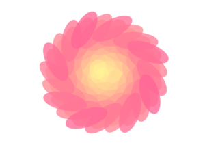
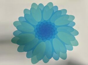
For my midterm project, I wanted to explore the mesmerizing nature of the Fibonacci spiral through a generative art system. I named the project “Fibonacci Dream” because it combines the beauty of mathematical spirals with dynamic, flowing petals that continuously change over time.

Concept and Artistic Vision:
The Fibonacci sequence and the golden angle have always fascinated me. I love how these mathematical principles appear in nature—from sunflowers to seashells. My goal was to mimic this natural elegance by creating a digital flower that grows and oscillates, combining organic movement with vibrant color palettes.

While researching Fibonacci spirals, I learned how deeply they connect to growth patterns in nature. This connection inspired me to build a visual system that transitions between different moods through rotating petals, oscillating sizes, and shifting color schemes. The final sketch uses a Fibonacci spiral to control the petal arrangement, creating a dynamic, mesmerizing flower with endless possibilities.

I used colors inspired by the natural world, with gradients of pink, yellow, blue, and green to evoke different emotional states. This color-changing feature makes the flower feel alive, as if it’s reacting to its environment.

Embedded Sketch:

https://editor.p5js.org/ha2297/full/Eo2Yntsgr

Coding Logic and Translation:

The logic behind “Fibonacci Dream” revolves around creating a dynamic, generative artwork using a Fibonacci spiral, with petals that oscillate, rotate, and change color over time. Here’s how each part of the code works:

  1. Fibonacci Spiral Arrangement
    The petals follow a Fibonacci spiral pattern, where each petal’s position is determined by an angle (137.5°) and a radius that grows as the square root of the petal index. This ensures that the petals are evenly spaced and spread outward in a natural spiral.
let angle = i * spiralAngle + time * 10;
let radius = sqrt(i) * 8;
let x = radius * cos(angle);
let y = radius * sin(angle);

2.Oscillation and Rotation
To give the petals life, they oscillate in size using the sine function, creating a smooth breathing effect. The petals also rotate in a spiral, and the speed of rotation is controlled by a user-adjustable slider.

let oscillation = map(sin(time + i), -1, 1, 0.8, 1.2);
let dynamicPetalLength = petalLength * oscillation;
let dynamicPetalWidth = petalWidth * oscillation;
rotate(angle + time);

3.Color Palettes
The code includes six color palettes that the user can switch between. Each palette uses gradients like pink to yellow or blue to green, adding variety to the artwork

switch (colorPalette) {
  case 0:
    colorVal = map(i, 0, numPetals, 255, 100); // Pink to yellow gradient
    fill(255, colorVal, 150, 200);
    break;
  // Other palettes...
}

4.User Interaction
Two sliders let the user control the rotation speed and zoom level, while a button switches between color palettes. These interactive elements make the artwork more engaging and customizable.

rotationSpeedSlider = createSlider(1, 50, 10);
zoomSlider = createSlider(0.5, 2, 1, 0.01);
colorChangeButton = createButton('Switch Color Palette');
colorChangeButton.mousePressed(switchColorPalette);

5. SVG Export
The artwork can be saved as an SVG image by pressing the ‘s’ key, allowing users to export and preserve the visual as a vector graphic.

function keyPressed(){
  if(key == "s" || key =="S"){
    save("image.svg");
  }
}

Code Snippet:

let oscillation = map(sin(time + i), -1, 1, 0.8, 1.2);
let dynamicPetalLength = petalLength * oscillation;
let dynamicPetalWidth = petalWidth * oscillation;

This code snippet is key to creating a “breathing” effect for the petals by making them grow and shrink over time. It uses the sin() function to generate oscillating values between -1 and 1, which are then mapped to a range between 0.8 and 1.2. This controls the petal size fluctuation, where petals shrink to 80% of their original size and grow to 120%, giving the effect of rhythmic breathing.

The combination of time and petal index (i) ensures that each petal oscillates with a slight variation, making the motion feel more organic. The mapped oscillation value is applied to both petal length and width, making the petals dynamically change in size.

This subtle movement brings the generative art to life. Without this oscillation, the flower would feel static and mechanical. The breathing effect, combined with the spiral pattern and color changes, adds a layer of depth, making the artwork more engaging and lifelike.

Challenges:

One of the biggest challenges was ensuring that the oscillation and rotation worked smoothly together, especially when combined with user input. It took several iterations to get the timing and size oscillation just right without breaking the flow of the petals.

Another challenge was handling the zoom function. Initially, zooming affected the positioning of the sliders and button, but I managed to fix this by anchoring them to the screen while zooming the canvas content independently.

Another issue that took some time to resolve was an error I encountered when trying to save the SVG file. Initially, I was using the following HTML file. However, I kept getting an error when trying to export the SVG. After some debugging, I realized that the issue was with the version of the p5.js SVG library I was using. I switched to an older version of the HTML file.The error occurred because the version of p5.js-svg I was initially using wasn’t compatible with the main p5.js version in my project. By switching to an older, more stable version, I was able to fix the issue and successfully save the SVG files.

Pen Plotting Experience:

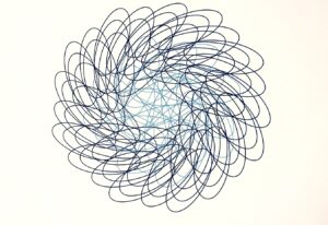
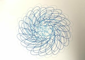
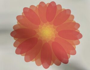
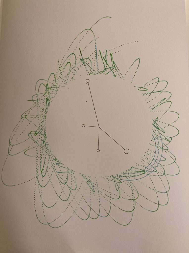
For the pen plotting experience, I initially wanted to make the image of the flower more interesting by dividing it into two color layers. I chose to have the inner layer in yellow and the outer layer in pink to create a subtle contrast. When I printed it with the pen plotter, I used light blue for the inner part and dark blue for the outer part.

Unfortunately, the video I recorded didn’t save. So, I decided to reprint the image with the same colors and setup. However, while printing the second layer (the outer part in dark blue), the ink started running out—not completely, but enough to create a faded effect. I thought about pausing the process to replace the pen, but I ended up liking the way it looked with the gradual fading. It gave the piece a more unique, unexpected quality, so I let the print finish as it was. This added an element of spontaneity to the final artwork that I hadn’t initially planned for, but really enjoyed.

First Version:
Second Version:
A3 Printed Images:

Areas for Improvement and Future Work
In future versions of this project, I have several ideas to improve and expand on:

  1. More User Interaction:

I want to add mouse or touch gestures, so users can control the flower’s rotation and zoom by dragging or pinching the screen. This would make the interaction more natural and fun, especially on touch devices like tablets.

2. 3D Elements:

I’m thinking of adding 3D effects to make the flower feel more immersive. For example, the petals could rise and fall, creating a sense of depth. This would make the flower seem more realistic, almost like it’s floating on the screen.
I also want to explore how natural forces like gravity or wind could affect the petals in 3D, adding a new layer of interaction and visual complexity.

3. Improving Pen Plotting:

I plan to refine the line quality for smoother transitions between layers of the flower when using the pen plotter.
I want to try different styles like stippling (dot patterns) or crosshatching (overlapping lines) to create shading and color effects similar to the digital version.
Experimenting with different pens and inks, like metallic or gradient colors, could help capture the vibrant look of the digital artwork in physical form.
These improvements will make the project more interactive and visually rich, both in the digital version and the pen-plotted version.

References: 

https://editor.p5js.org/xiao2202/sketches/vkHJQX4gy

https://github.com/Jttpo2/flowers

Midterm Progress – Khalifa Alshamsi

Concept and Idea

The main idea behind my midterm project was to create a generative landscape that evolves over time. This would allow users to interact with the scene via a slider and explore the beauty of dynamic elements like a growing tree, shifting daylight, and a clean, natural environment. I wanted to focus on simple yet beautiful visual aesthetics while ensuring interactivity and real-time manipulation, aiming for a calm user experience.

Code Development and Functionality

Time Slider: The time slider dynamically adjusts the time of day, transitioning from morning to night. The background color shifts gradually, and the sun and moon rise and fall in sync with the time value.

Main Tree Rendering: The project features a main tree at the center of the canvas. The tree grows gradually, with branches and leaves adjusting based on predefined patterns to give it a natural look. I worked hard to make sure that the tree’s behavior felt organic.

SVG Export:  One of the key functionalities of this project is the SVG Export feature, which allows users to save a snapshot of the generated landscape in high-quality vector format. This export option enables users to preserve the art they create during the interaction, offering a way to take a piece of the generative landscape.

Code Snippets Explanation:

Background Color

function updateBackground(timeValue, renderer = this) {
  let sunriseColor = color(255, 102, 51);
  let sunsetColor = color(30, 144, 255);
  let nightColor = color(25, 25, 112);

  let transitionColor = lerpColor(sunriseColor, sunsetColor, timeValue / 100);
  
  if (timeValue > 50) {
    transitionColor = lerpColor(sunsetColor, nightColor, (timeValue - 50) / 50);
    c2 = lerpColor(color(255, 127, 80), nightColor, (timeValue - 50) / 50);
  } else {
    c2 = color(255, 127, 80);
  }

  setGradient(0, 0, W, H, transitionColor, c2, Y_AXIS, renderer);
}

This part of the code gradually shifts the background color from sunrise to sunset and into night, giving the entire scene a fluid sense of time passing. It was highly rewarding to see the colors change with smooth transitions based on user input.

Tree Shape Rendering

At the heart of this project is the main tree, which dynamically grows and changes shape as part of the landscape. The goal is to have the tree shift in both its shape and direction each time it is rendered, adding an element of unpredictability and natural randomness. The tree is designed to grow recursively, with branches and leaves adjusting their position and angles in a way that mimics the organic growth patterns found in nature.

function drawTree(depth, renderer = this) {
  renderer.stroke(139, 69, 19);
  renderer.strokeWeight(3 - depth);  // Adjust stroke weight for consistency
  branch(depth, renderer);  // Call the branch function to draw the tree
}

function branch(depth, renderer = this) {
  if (depth < 10) {
    renderer.line(0, 0, 0, -H / 15);
    renderer.translate(0, -H / 15);

    renderer.rotate(random(-0.05, 0.05));

    if (random(1.0) < 0.7) {
      renderer.rotate(0.3);
      renderer.scale(0.8);
      renderer.push();
      branch(depth + 1, renderer);  // Recursively draw branches
      renderer.pop();
      
      renderer.rotate(-0.6);
      renderer.push();
      branch(depth + 1, renderer);
      renderer.pop();
    } else {
      branch(depth, renderer);
    }
  } else {
    drawLeaf(renderer);  // Draw leaves when the branch reaches its end
  }
}

Currently, the tree renders with the same basic structure every time the canvas is started. The recursive branch() function ensures that the tree grows symmetrically, with each branch extending and splitting at controlled intervals. The randomness in the rotation(rotate()) creates slight variations in the angles of the branches, but overall the tree maintains a consistent shape and direction.

This stable and predictable behavior is useful for ensuring that the tree grows in a visually balanced way, without unexpected distortions or shapes. The slight randomness in the angles gives it a natural feel, but the tree maintains its overall form each time the canvas is refreshed.

This part of the project focuses on the visual consistency of the tree, which helps maintain the aesthetic of the landscape. While the tree doesn’t yet shift in shape or direction with every render, the current design showcases the potential for more complex growth patterns in the future.

Challenges 

Throughout the development of this project, several challenges arose, particularly regarding the tree shadow, sky color transitions, tree shape, and ensuring the SVG export worked correctly. While I’ve made significant progress, overcoming these obstacles required a lot of experimentation and adjustment to ensure everything worked together harmoniously.

1. Tree Shadow Rendering One of the key challenges was handling the tree shadow. I wanted the shadow to appear on the canvas in a way that realistically reflects the position of the sun or moon. However, creating a shadow that behaves naturally while keeping the tree itself visually consistent was tricky. The biggest challenge came when trying to manage the transformations (translate()) and rotate()) needed to properly position the shadow, while ensuring that it didn’t overlap awkwardly with the tree or its branches.

I was also careful to ensure the shadow was neglected in the SVG export, as shadows often don’t look as polished in vector format. Balancing these two render modes was a challenge, but I’m happy with the final result where the shadow appears correctly on the canvas but is removed when saved as an SVG.

2. Sky Color Transitions Another challenge was smoothly transitioning the sky color based on the time of day, controlled by the slider. Initially, it was difficult to ensure the gradient between sunrise, sunset, and nighttime felt natural and visually appealing. The subtleness required in blending colors across the gradient presented some challenges in maintaining smooth transitions without sudden jumps which happened way more then I needed it to.

Using the lerpColor() function to blend the sky colors as the slider changes allowed me to create a more cohesive visual experience. Finding the right balance between the colors and timing took a lot of trial and error. Ensuring this transition felt smooth was critical to the overall atmosphere of the scene.

3. SVG File Export One of the more technical challenges was ensuring that the SVG export functionality worked seamlessly, capturing the landscape in vector format without losing the integrity of the design. Exporting the tree and sky while excluding the shadow required careful handling of the different renderers used for canvas and SVG. The transformations that worked for the canvas didn’t always translate perfectly to the SVG format, causing elements to shift out of place or scale incorrectly.

Additionally, I needed to ensure that the tree was positioned correctly in the SVG file, especially since the translate() function works differently in SVG. Ensuring that all elements appeared in their proper positions while maintaining the overall aesthetic of the canvas version was a delicate process.

4. Switching Between SVG Rendering and Canvas with the full explanation

In the project, switching between SVG rendering and canvas rendering is essential to ensure the artwork can be viewed in real-time on the canvas and saved as a high-quality SVG file. These two rendering contexts behave differently, so specific functions must handle the drawing process correctly in each mode.

Overview of the Switch

  • Canvas Rendering: This is the default rendering context where everything is drawn in real-time on the web page. The user interacts with the canvas, and all elements (like the tree, sky, and shadows) are displayed dynamically.
  • SVG Rendering: This mode is activated when the user wants to save the artwork as a vector file (SVG). Unlike the canvas, SVG is a scalable format, so certain features (such as shadows) need to be omitted to maintain a clean output. SVG rendering requires switching to a special rendering context using createGraphics(W, H, SVG).

Code Implementation for the Switch

The following code shows how the switch between canvas rendering and SVG rendering is handled:

// Function to save the canvas as an SVG without shadow
function saveCanvasAsSVG() {
  let svgCanvas = createGraphics(W, H, SVG);  // Use createGraphics for SVG rendering
  
  redrawCanvas(svgCanvas);  // Redraw everything onto the SVG canvas
  
  save(svgCanvas, "myLandscape.svg");  // Save the rendered SVG

  svgCanvas.remove();  // Remove the SVG renderer to free memory
}

Here’s how the switching process works

  1. Creates an SVG Graphics Context: When saving the artwork as an SVG, we create a separate graphics context using createGraphics(W, H, SVG). This context behaves like a normal p5.js canvas, but it renders everything as an SVG instead of raster graphics. The dimensions of the SVG are the same as the canvas (W and H)
  1. Redraws Everything on the SVG: After creating the SVG context, we call the redrawCanvas(svgCanvas)  function to redraw the entire scene but on the SVG renderer. This ensures that everything (like the tree and background) is rendered as part of the vector file, but without including elements like shadows, which may not look good in an SVG.
  2. Save the SVG: Once everything has been drawn on the svgCanvas, the save() This function saves the SVG file locally on the user’s device. This ensures that the entire artwork is captured as a scalable vector file, preserving all the details for further use.
  3. Remove the SVG Renderer: After saving the SVG, we call svgCanvas.remove() to clean up the memory and remove the SVG renderer. This is essential to avoid keeping the unused graphics context in memory once the file has been saved.

Redrawing the Canvas and SVG Separately

The key part of this process is in the redrawCanvas() function, which determines whether the elements are drawn on the canvas or the SVG renderer:

function redrawCanvas(renderer = this) {
  if (renderer === this) {
    background(135, 206, 235);  // For the normal canvas
  } else {
    renderer.background(135, 206, 235);  // For the SVG canvas
  }

  let timeValue = timeSlider.value();  // Get the slider value for background time changes
  updateBackground(timeValue, renderer);
  updateSunAndMoon(timeValue, renderer);

  // Draw tree and other elements
  if (renderer === this) {
    // Draw the main tree on the canvas with shadow
    push();
    translate(W / 2, H - 50);
    randomSeed(treeShapeSeed);
    drawTree(0, renderer);
    pop();

    // Draw shadow only on the canvas
    let shadowDirection = sunX ? sunX : moonX;
    let shadowAngle = map(shadowDirection, 0, width, -PI / 4, PI / 4);
    push();
    translate(W / 2, H - 50);
    rotate(shadowAngle);
    scale(0.5, -1.5);  // Flip and adjust shadow scale
    drawTreeShadow(0, renderer);
    pop();
  } else {
    // Draw the main tree in SVG without shadow
    renderer.push();
    renderer.translate(W / 2, H - 50);  // Translate for SVG
    randomSeed(treeShapeSeed);
    drawTree(0, renderer);
    renderer.pop();
  }
}
  1. Check the Renderer: The redrawCanvas(renderer = this) function takes in a renderer argument, which defaults to this (the main canvas). However, when the function is called for SVG rendering, the renderer becomes the svgCanvas.
  1. Background Handling: The background is drawn differently depending on the renderer. For the canvas, the background is rendered as a normal raster graphic (background(135, 206, 235), but for SVG rendering, it uses renderer.background(), which applies the background color to the vector graphic.
  2. Tree Rendering: The drawTree() function is called for both canvas and SVG rendering. However, in the SVG mode, the shadow is omitted to produce a cleaner vector output. This is handled by using conditional checks (if (renderer === this)  to ensure that the shadow is only drawn when rendering on the canvas.
  3. Shadow Omission in SVG: To maintain a clean SVG output, shadows are only drawn in the canvas rendering mode. The drawTreeShadow() function is conditionally skipped in the SVG renderer to prevent unnecessary visual clutter in the vector file.
Why the Switch is Necessary

Switching between canvas rendering and SVG rendering is crucial for several reasons:

  • Canvas: Provides real-time, interactive feedback as the user adjusts the scene (e.g., changing the time of day via a slider). Shadows and other elements are rendered in real-time to enhance the user experience.
  • SVG: This is a high-quality, scalable vector output. SVGs are resolution-independent, so they retain detail regardless of size. However, certain elements like shadows might not translate well to the SVG format, so these are omitted during the SVG rendering process.

This approach allows the project to function interactively on the canvas while still allowing users to export their creations in a high-quality format constantly.

Full Code

let W = 650;
let H = 450;

let timeSlider; 
let saveButton; 
let showMountains = false; 
let showTrees = false; 
let treeShapeSeed = 0;
let mountainShapeSeed = 0;
let sunX; 
let sunY; 
let moonX;
let moonY; 
let mountainLayers = 2;
let treeCount = 8;

const Y_AXIS = 1;
let groundLevel = H - 50;

function setup() {
  createCanvas(W, H); 
  background(135, 206, 235);

  timeSlider = createSlider(0, 100, 50);
  timeSlider.position(200, 460);
  timeSlider.size(250);
  timeSlider.input(updateCanvasWithSlider);  // Trigger update when the slider moves
  saveButton = createButton('Save as SVG');
  saveButton.position(550, 460);
  saveButton.mousePressed(saveCanvasAsSVG);

  noLoop();  // Only redraw on interaction
  redrawCanvas();  // Initial drawing
}

// Update canvas when the slider changes
function updateCanvasWithSlider() {
  redrawCanvas();  // Call redrawCanvas to apply slider changes
}

// Function to save the canvas as an SVG without shadow
function saveCanvasAsSVG() {
  let svgCanvas = createGraphics(W, H, SVG);  // Use createGraphics for SVG rendering

  redrawCanvas(svgCanvas);  // Redraw everything onto the SVG canvas

  save(svgCanvas, "myLandscape.svg");

  svgCanvas.remove();
}

// Function to redraw the canvas content on a specific renderer (SVG or regular canvas)
function redrawCanvas(renderer = this) {
  if (renderer === this) {
    background(135, 206, 235);  // For the normal canvas
  } else {
    renderer.background(135, 206, 235);  // For the SVG canvas
  }
  
  let timeValue = timeSlider.value();  // Get the slider value for background time changes
  updateBackground(timeValue, renderer);
  updateSunAndMoon(timeValue, renderer);

  drawSimpleGreenGround(renderer);
  // Handle the main tree drawing separately for canvas and SVG
  if (renderer === this) {
    // Draw the main tree on the canvas
    push();
    translate(W / 2, H - 50);  // Translate for canvas
    randomSeed(treeShapeSeed);
    drawTree(0, renderer);
    pop();

    // Draw shadow on the main canvas
    let shadowDirection = sunX ? sunX : moonX;
    let shadowAngle = map(shadowDirection, 0, width, -PI / 4, PI / 4);

    push();
    translate(W / 2, H - 50);  // Same translation as the tree
    rotate(shadowAngle);       // Rotate based on light direction
    scale(0.5, -1.5);          // Scale and flip for shadow effect
    drawTreeShadow(0, renderer);
    pop();
  } else {
    // Draw the main tree in SVG without shadow
    renderer.push();
    renderer.translate(W / 2, H - 50);  // Translate for SVG
    randomSeed(treeShapeSeed);
    drawTree(0, renderer);
    renderer.pop();
  }
}


// Commented out the tree shadow (kept for the main canvas)
function drawTreeShadow(depth, renderer = this) {
  renderer.stroke(0, 0, 0, 80);  // Semi-transparent shadow
  renderer.strokeWeight(5 - depth);  // Adjust shadow thickness
  branch(depth, renderer);  // Use the branch function to draw the shadow
}

// Update background colors based on time
function updateBackground(timeValue, renderer = this) {
  let sunriseColor = color(255, 102, 51);
  let sunsetColor = color(30, 144, 255);
  let nightColor = color(25, 25, 112);

  let transitionColor = lerpColor(sunriseColor, sunsetColor, timeValue / 100);
  
  if (timeValue > 50) {
    transitionColor = lerpColor(sunsetColor, nightColor, (timeValue - 50) / 50);
    c2 = lerpColor(color(255, 127, 80), nightColor, (timeValue - 50) / 50);
  } else {
    c2 = color(255, 127, 80);
  }

  setGradient(0, 0, W, H, transitionColor, c2, Y_AXIS, renderer);
}

// Update sun and moon positions
function updateSunAndMoon(timeValue, renderer = this) {
  if (timeValue <= 50) {
    sunX = map(timeValue, 0, 50, -50, width + 50);
    sunY = height * 0.8 - sin(map(sunX, -50, width + 50, 0, PI)) * height * 0.5;
    
    renderer.noStroke();
    renderer.fill(255, 200, 0);
    renderer.ellipse(sunX, sunY, 70, 70); 
  }
  
  if (timeValue > 50) {
    moonX = map(timeValue, 50, 100, -50, width + 50);
    moonY = height * 0.8 - sin(map(moonX, -50, width + 50, 0, PI)) * height * 0.5;
    
    renderer.noStroke();
    renderer.fill(200);
    renderer.ellipse(moonX, moonY, 60, 60);
  }
}

// Create a gradient effect for background
function setGradient(x, y, w, h, c1, c2, axis, renderer = this) {
  renderer.noFill();

  if (axis === Y_AXIS) {
    for (let i = y; i <= y + h; i++) {
      let inter = map(i, y, y + h, 0, 1);
      let c = lerpColor(c1, c2, inter);
      renderer.stroke(c);
      renderer.line(x, i, x + w, i);
    }
  }
}

// Draw the green ground at the bottom
function drawSimpleGreenGround(renderer = this) {
  renderer.fill(34, 139, 34);
  renderer.rect(0, H - 50, W, 50);
}

// Draw the main tree
function drawTree(depth, renderer = this) {
  renderer.stroke(139, 69, 19);
  renderer.strokeWeight(3 - depth);  // Adjust stroke weight for consistency
  branch(depth, renderer);
}

// Draw tree branches
function branch(depth, renderer = this) {
  if (depth < 10) {
    renderer.line(0, 0, 0, -H / 15);
    renderer.translate(0, -H / 15);

    renderer.rotate(random(-0.05, 0.05));

    if (random(1.0) < 0.7) {
      renderer.rotate(0.3);
      renderer.scale(0.8);
      renderer.push();
      branch(depth + 1, renderer);
      renderer.pop();
      
      renderer.rotate(-0.6);
      renderer.push();
      branch(depth + 1, renderer);
      renderer.pop();
    } else {
      branch(depth, renderer);
    }
  } else {
    drawLeaf(renderer);
  }
}

// Draw leaves on branches
function drawLeaf(renderer = this) {
  renderer.fill(34, 139, 34);
  renderer.noStroke();
  for (let i = 0; i < random(3, 6); i++) {
    renderer.ellipse(random(-10, 10), random(-10, 10), 12, 24);  // Increase leaf size
  }
}

Sketch

Future Improvements

As the project continues to evolve, several exciting features are planned that will enhance the visual complexity and interactivity of the landscape. These improvements aim to add depth, variety, and richer user engagement, building upon the current foundation.

1. Mountain Layers

A future goal is to introduce mountain layers into the landscape’s background. These mountains will be procedurally generated and layered to create a sense of depth and distance. Users will be able to toggle different layers, making the landscape more immersive. By adding this feature, the project will feel more dynamic, with natural textures and elevation changes in the backdrop.

The challenge will be to ensure these mountain layers integrate smoothly with the existing elements while maintaining a clean, balanced visual aesthetic.

2. Adding Background Trees

In future versions, I plan to implement background trees scattered across the canvas. These trees will vary in size and shape, adding diversity to the forest scene. By incorporating multiple trees of different types, the landscape will feel fuller and more like a natural environment.

The goal is to introduce more organic elements while ensuring that the visual focus remains on the main tree in the center of the canvas.

3. Shifting Tree Shape

Another key feature in development is the tree’s ability to shift shape and direction dynamically in a random pattern. In the future, the tree’s branches will grow differently each time the canvas is refreshed, making each render unique. This will add a level of unpredictability and realism to the scene, allowing the tree to behave more like its real-life counterpart, which never grows the same way twice.

Careful tuning will be required to ensure the tree maintains its natural appearance while introducing variations that feel organic.

4. Enhanced Interactivity

I also aim to expand the project’s interactive elements. Beyond the current time slider, future improvements will allow users to manipulate other aspects of the landscape, such as the number of trees, the height of the mountains, or even the size and shape of the main tree. This will allow users to have a greater impact on the generative art they create, deepening their connection with the landscape.

Sources:

https://p5js.org/reference/p5/createGraphics/

https://github.com/zenozeng/p5.js-svg

https://www.w3.org/Graphics/SVG/

https://github.com/processing/p5.js/wiki/

Midterm | Unnatural Coolors

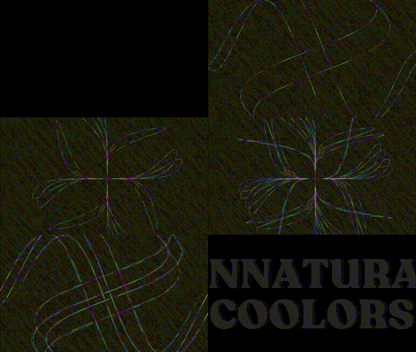
Unnatural Coolors

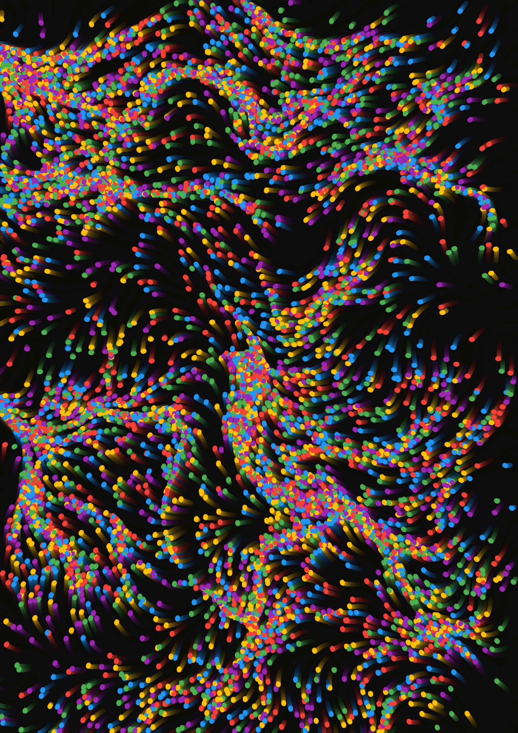
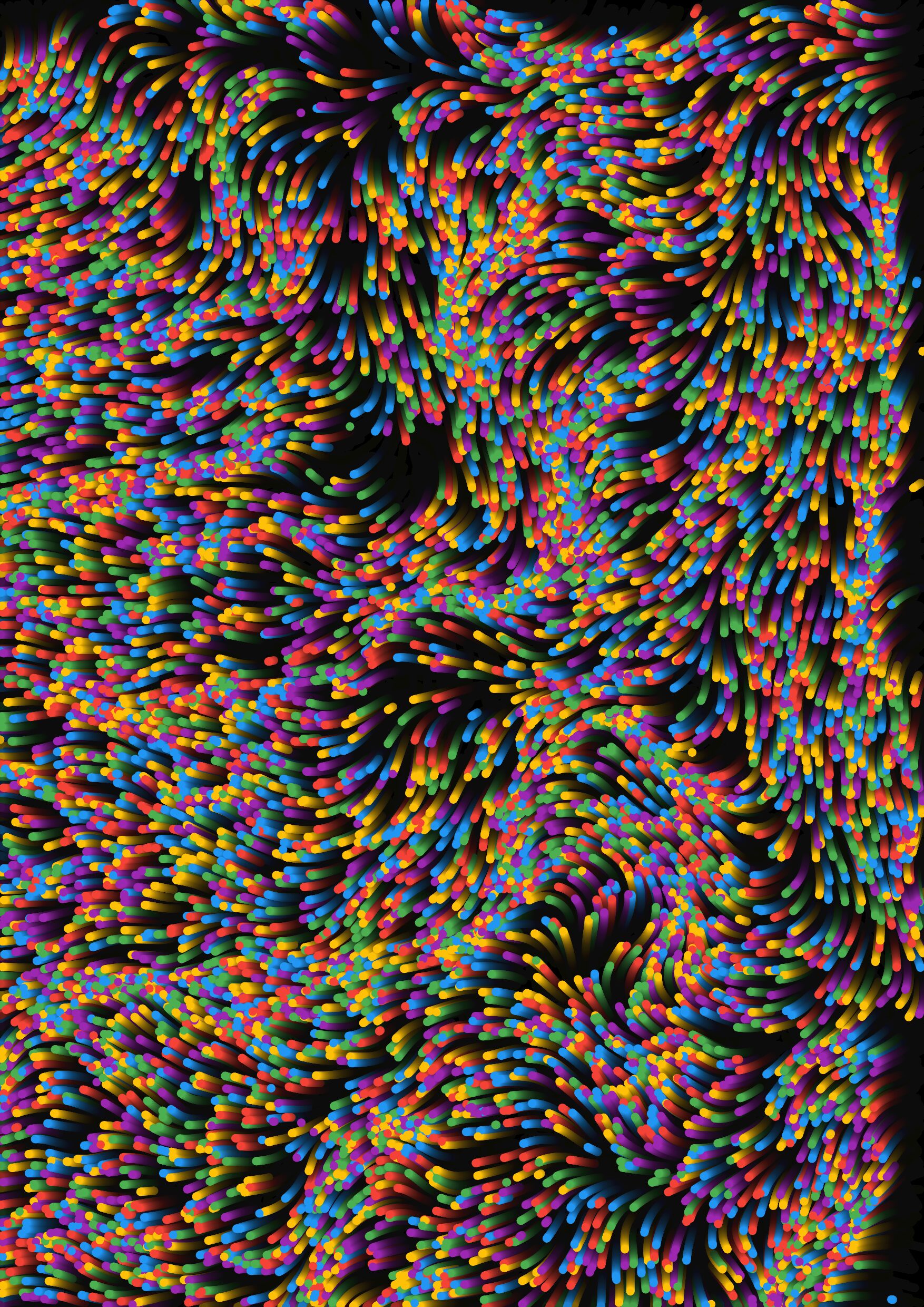
Unnatural Coolors is a p5.js project that simulates a select few parametric equations hand-picked by the author, (me). This project uses a p5.js vector framework to plot the equations. In addition to the standard mathematical plotting, Unnature Coolors also simulate how wind, and Perlin noise, affect the whole drawing. Essentially, a slight change, inevitably, creates a significantly different outcome. Mimicking the common occurrences of randomness in nature.

The smallest decision in life can at times, lead to the biggest outcome.

Concepts & Inspiration

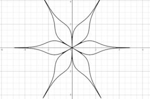
I have always been fascinated by the unique patterns that appear in mathematical models, which often also occur as part of nature itself. As I scoured the internet and math textbooks alike, I found parametric equations to emit its own beauty. Instead of defining x over y in a cartesian coordinate, parametric equations define x and y as functions of a third parameter, t (time). They help us find the path, direction, and position of an object at any given time. This also means, the equations work in any dimensions!

As I explored the internet for inspiration, I came across a Swiss artist, Ilhan Zulji, who studied randomness and implemented it into his work, creating a unique generative art style that reminds me of an ‘ordered chaos’. His work consists of creating shapes, and patterns, that are based on mathematical models, adding randomness into it, while maintaining some kind of structure and balance to make the visual appealing. Including the interactive elements, which allow the user to control the randomness to a certain degree, adds another layer of immersiveness to the viewing experience.

How Unnatural Coolors Works

The Particle class is responsible for the creation of particles drawn on the sketch. It takes the predetermined equation and translates it into the x-position, and y-position of the particles. To achieve a smooth motion, I put some offset between each particle. The particles are also affected by external forces from noise and wind, which makes them more dynamic. Then, between the distance of two particles, I formed a stroke of lines.

class Particle {
  constructor(timeOffset, xEquation, yEquation, lifetime) {
    this.timeOffset = timeOffset;
    this.prevPos = null;
    this.xEquation = xEquation;
    this.yEquation = yEquation;
    this.lifetime = lifetime; // Lifetime in frames
    this.maxLifetime = lifetime; // Store the original max lifetime
  }

Colors are produced by manipulating HSB color values. Originally, I wanted the colors to be a smooth gradient changing between one and another. However, after some testing, I decided that random colors between each particle were nicer.

display() {
    if (this.lifetime <= 0) return; // Skip rendering if lifetime is over
    
    // Calculate alpha based on remaining lifetime
    let alphaValue = map(this.lifetime, 0, this.maxLifetime, 0, 255); // Fade from 255 to 0
    //let hueValue = map(t, -6, 6, 0, 360); // Changing color over time
    let hueValue = random(0, 360) 
    stroke(hueValue, 100, 100, alphaValue); // HSB color with fading alpha

External forces, such as the wind and noise, are pre-calculated and initialized beforehand. These values are set by the slider below the canvas. This is done to ensure that the drawings start from the determined positions when the canvas starts or is refreshed.

// Wind slider with only 3 states (1 = left, 2 = no wind, 3 = right)
windSlider = createSlider(1, 3, 2);
windSlider.position(10, canvasBottom + 80);

noiseSlider = createSlider(0, 1, 0, 0.1);
noiseSlider.position(10, canvasBottom + 110);

let windLabel = createDiv('Wind');
windLabel.position(160, canvasBottom + 78);

let noiseLabel = createDiv('Noise');
noiseLabel.position(160, canvasBottom + 108);

initParticles();
Beyond Digital

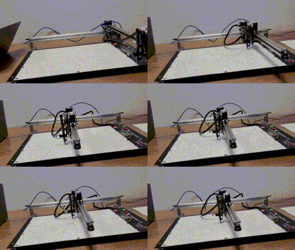
Every artist dreams of having their work come to life. Unnatural Coolors was able to be brought to life by using the pen plotter. Below is a timelapse of the whole process of converting and drawing the best shape.

Challenges & Improvements

Most of the equations that I used are all in a single quadrant. Initially, I was confused as to why p5.js does not want to rotate the way I wanted it to be. To make sure that it forms the shape I desired, translate() was used three times, rotating 90 degrees each time.

In the beginning, I played around with fading the background a lot. By fading the background, I could ‘animate’ the motions of the shape plotting. However, after implementing multiple offset particles, it became apparent that this idea was no longer working. To combat this, I removed the background refresh, and let the canvas draw over instead.

I would love to see how this art can be generated using equations on the fly for future improvements. What I mean by this is that instead of predetermined equations, I want the users to tweak a certain equation, write their own, and plot unique shapes.

Check out the sketch here!

Useful Resources

# Drawing Parametric Equations – Umit Sen 

# Drawing Flow Fields with Vectors – Colorful Coding

# Quadio – Ikko. graphics 

# Audio Reactive Visuals – Leksha Yankov

# Audio Reactive Visuals CS Project – Austin Zhang

Midterm Project – Generative Clock

Concept

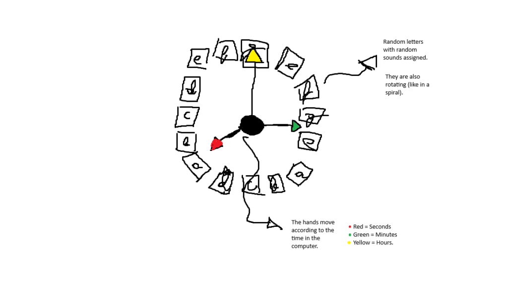
This was a sketch that took some time to fully realize what my final concept was. First, I thought about being inspired by my sketch “2000s qwerty” and integrate key caps into the midterm with a clock. Although, when I finished a quick draft of it, I did not like the end result: It was very uninspired.

Figure 1. Initial sketch.

However, the clock functionality was giving promising results and more ideas.

After deleting the key caps out of the sketch, I started experimenting with the clock I made, trying to understand what kind of creative variations I could do with it. After some time of thinking, I decided that it was best to add certain functionalities to each hand, but at the same time, that each function somehow helps in filling the background to generate the silhouette of a clock. The end result can be seen in the following sketch.

Sketch

Note: By clicking on the canvas, it will generate a .svg file of what is currently seen on screen. Likewise, by pressing the space bar, the color scheme will toggle between either colorful (the default) or black and white.

Full-screen version: Fullscreen version of “Generative Clock v1.0”

The functionality

Since the idea of the midterm was to implement different concepts we have seen so far in class, I decided to add each one in a “natural” manner. The functionalities are the following:

      1. Vectors: Everything is composed by vectors.
      2. Clock hands using angles: These, according to the system’s time, will move accordingly as if it was a real analog clock. The way that the position of the hands is determined is by, first, catching the current time of the system, to then translate and map the vector values of each hand to an angle (with the help of theta).
      3. Physics: The sketch possesses gravity, acceleration, and attraction. For example, every time a second passes, a tiny particle will spawn in the X and Y coordinates of the millisecond hand. After than, they will get attracted to the seconds hand and fly around it using the aforementioned physics.
      4. Perlin Noise: The particles that fly around the seconds hand will have their colors changed using the Perlin noise, which grabs the current system time to move smoothly in the RGB values.
      5. Particles system: Each particle that loops around the seconds hand will get deleted after some time, to avoid consuming more resources of the computer.

Highlight of the code I am proud of

The hardest part of this code was translating the system time to the accurate position of the clock’s hand, since it needed precise values in order to be properly represented using angles:

//Move the hands in a circular motion, according to system time.
update(hours, minutes, seconds, milliseconds){


    // Convert polar to cartesian  (Taken from an example from class).
    this.position = p5.Vector.fromAngle(this.theta);
    this.position.mult(this.r);

    if (this.type_of_hand == "hours"){
        this.theta = map(hours, 0, 198, -51.8, 51.8);   //-51.8 seems to be the value to simulate a clock.

    } else if (this.type_of_hand == "minutes"){
        this.theta = map(minutes, 0, 1000, -51.8, 51.8);
    }

    else if (this.type_of_hand == "seconds"){
        this.theta = map(seconds, 0, 1000, -51.8, 51.8);
    }
    
    else if (this.type_of_hand == "milliseconds”){
        this.theta = map(milliseconds, 0, 15800, -51.8, 51.8);
    }
}

Images

Figure 2. Clock without the generative background.
Figure 3. Clock with the generative background in colorful mode.
Figure 4. Clock with generative background in black and white mode.

Pen Plotting

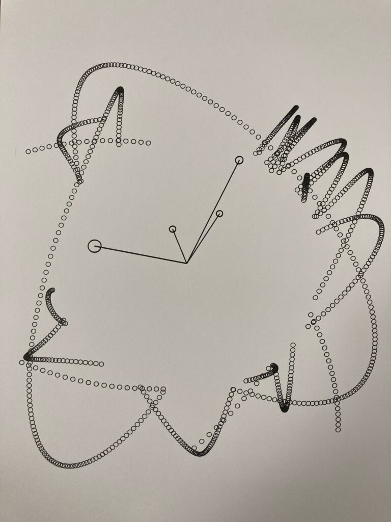
For the pen plotting in a A3 paper, I had to create a different version in order to be easily drawn, since the original version would create a .svg file that would take too much time to plot. This involved taking some artistic decisions, such as altering the pattern and physics to avoid creating many circles.

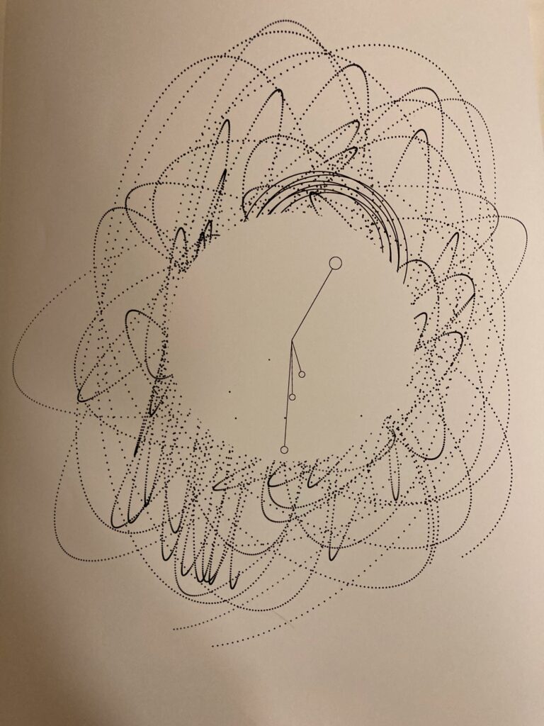
Figure 5. Generative Clock made with pen plotter.

Printed version

For the printed version, the  was used to develop the following:

Figure 6. Black and white version of the Generative Clock printed on a A3 paper.
Figure 7. Colorful version of the Generative Clock printed on a A3 paper.

Reflection and future improvements

I am happy with the progress so far for this midterm. The concepts that I applied from class (in my opinion) seem to integrate seamlessly with the concept of the project. Although, one thing that I would like to implement is a functionality for the hours hand, although it would seem a bit unnecessary since it will take too long to move. Likewise, I would like to implement another feature which could help the Canva appear more interesting visually, but I have yet to come with new ideas.

Used Sources

Midterm Project – Branches of Motion

Concept and Artistic Vision
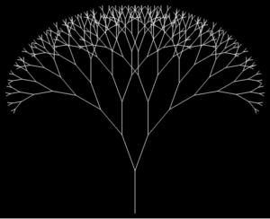
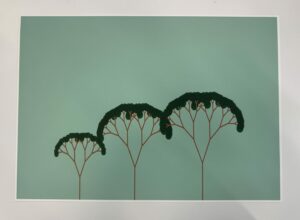
For my midterm project, I wanted to explore how trees grow and branch out, which led me to create a generative art piece inspired by fractals in nature. Fractals are patterns that repeat themselves on smaller scales, like how branches grow from a tree trunk or veins spread in a leaf. This idea of repeating structures fascinated me, and I thought it would be fun to create a digital version of it.

My goal was to make the tree interactive, allowing users to control how the branches form in real-time. By moving the mouse, users can change the angle of the branches, making each tree unique based on their input. The inspiration for this project came from my curiosity about natural patterns and how I could recreate them using code. I researched fractal geometry and recursion, which are mathematical concepts often found in nature, and used this knowledge to guide my design.

Embedded Sketch and Link

https://editor.p5js.org/maryamalmatrooshi/sketches/GuKtOJDRf

Coding Translation and Logic
To create the tree, I used a recursive function, which is a function that calls itself to repeat the same process multiple times. This method was perfect for drawing a fractal tree because the branches of a tree naturally split into smaller and smaller branches. The main function that drives the sketch is branch(), which takes the current branch length, draws it, and then calls itself to draw smaller branches at an angle. The recursion stops when the branches become too small. This allowed me to create a natural branching structure with only a few lines of code.

The logic behind the tree’s growth is connected to the user’s mouse movements. I mapped the mouse’s X position to the angle of the branches, so when you move the mouse left or right, the branches change their direction. This made the tree feel interactive and dynamic. From class, I applied concepts of randomness and noise to slightly change how the branches grow, which gave the tree a more organic, natural feel. I also used vector transformations, like translate() and rotate(), to position and rotate each branch correctly on the canvas.

Parts I Am Proud Of and Challenges Overcome
One part of the project I’m really proud of is how smoothly the tree responds to mouse movement. I wanted the interaction to feel natural, without any jittering or sharp movements, which can be tricky when working with recursion. By carefully mapping the mouseX position to the branch angle, I made sure the transitions between the branches are smooth, even when the mouse is moved quickly. This adds to the overall experience, making the tree feel more alive.

One of the main challenges I faced was getting the recursion right without creating overlapping branches or cluttered patterns. When working with recursive functions like branch(), there’s a risk that the drawing can become messy if the angles or lengths aren’t carefully controlled. I solved this by setting a minimum branch length and adjusting the angle based on the mouse position, so the branches only grow within a controlled range.

Here’s a snippet of the code that handles the recursion for the branches:

function branch(len) {
  line(0, 0, 0, -len);  // Draw the current branch
  translate(0, -len);  // Move to the end of the branch

  if (len > 8) {  // Only keep branching if the length is greater than 8
    push();  // Save the current state
    rotate(angle);  // Rotate based on mouse position
    branch(len * 0.67);  // Recursively draw a smaller branch
    pop();  // Restore the state

    push();  // Save the state again for the opposite branch
    rotate(-angle);  // Rotate in the opposite direction
    branch(len * 0.67);  // Recursively draw the other branch
    pop();  // Restore the state
  }
}

Overcoming these challenges made the project more rewarding and taught me how to refine recursive logic for smoother results.

Pen Plotting Process
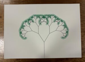
For the pen plotting process, I used my second draft sketch, which was a simplified version of the tree without user interaction. In this version, the tree grows and sways left and right, as if blown by the wind, with the branches and leaves already attached. To prepare it for plotting, I saved a specific moment of the sketch as an SVG file. I then imported the file into Inkscape for further editing.

In Inkscape, I layered the different parts of the tree to make it easier to plot in multiple colors. Specifically, I grouped all the branches and leaves together on one layer, and the stem on a separate layer. This allowed me to plot the stem first in black and then the branches and leaves in green. Using layers was crucial to make sure each part of the tree was plotted clearly without overlapping or messy transitions between colors.

This process of layering and color separation helped me create a clean, visually striking pen plot, where the black stem contrasts with the green branches and leaves.

Link to my second draft for reference: https://editor.p5js.org/maryamalmatrooshi/sketches/K0YQElaqm

Pen Plotted Photograph and Sped up Video

Areas for Improvement and Future Work
One improvement I wanted to add to my sketch was background music that plays while the user interacts with the tree. I think adding a calming, nature-inspired sound would make the experience feel even more alive and immersive. This would enhance the interaction, making it feel like the tree is part of a more natural, dynamic environment.

Regarding the pen plotting process, I faced a challenge with the way the leaves are drawn. In my sketch, the leaves are represented as ellipses that are filled in. However, the plotter only draws strokes, which means my leaves were outlined ellipses instead of being filled in. I’d like to improve this by experimenting with different leaf shapes that work better with the plotter. For example, I could create custom leaf shapes that are more suitable for stroke-only plotting, ensuring the final result looks more like natural leaves.

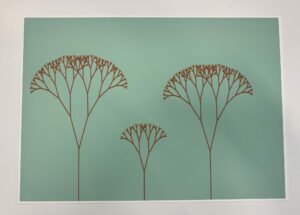
Two A3 Printed Images

References

https://editor.p5js.org/YuanHau/sketches/ByvYWs9yM

https://github.com/latamaosadi/p5-Fractal-Tree

https://github.com/adi868/Fractal-Trees

https://stackoverflow.com/questions/77929395/fractal-tree-in-p5-js

Midterm- Sankofa: Patterns of the Past

Concept and Artistic Vision

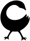
The concept of Sankofa, derived from the Akan people of Ghana, embodies the idea that one should remember the past to foster positive progress in the future.   The Akan tribe, part of the larger Ashanti (or Asante) group, encapsulates a rich cultural heritage that emphasizes the importance of history and self-identity. The word “Sankofa” translates to “to retrieve,” embodying the proverb, “Se wo were fi na wosankofa a yenkyi,” meaning “it is not taboo to go back and get what you forgot.” This principle highlights that understanding our history is crucial for personal growth and cultural awareness.
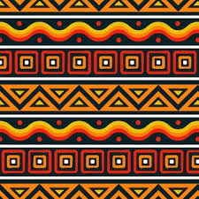
This philosophy has greatly inspired my project. Adinkra symbols, with their deep historical roots and intricate patterns, serve as a central element of my work. These symbols carry meanings that far surpass my personal experiences, urging me to look back at my heritage. I aim to recreate these age-old symbols in a modern, interactive format that pays homage to their origins. It’s my way of going back into the past to get what is good and  moving forward with it.
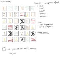
 

Embedded Sketch

Images

 Coding Translation and Logic

The core of my sketch is a dynamic grid-based visualization that reflects Adinkra symbols, infused with movement and interaction through music. Here’s how I approached this creative endeavor:

Creating a Grid Layout

I divided the canvas into a grid structure, with each cell serving as a small canvas for a unique Adinkra symbol. I utilized a 2D array to manage the placement of these symbols efficiently.

    • I defined variables for columns and rows to control the grid structure.
    • I calculated cellSize for evenly spaced symbols.
let x = currentCol * cellSize;

let y = currentRow * cellSize;
Pattern Assignment

I created an array of Adinkra patterns, randomly assigning them to each grid cell for a vibrant, ever-evolving display.

    • I looped through the grid and calling drawPattern() to render each symbol.
function initializePatterns() {
  patterns = [
    drawThickVerticalLines,
    drawNestedTriangles,
    drawSymbols,
    drawZebraPrint,
    drawDiamondsInDiamond,
    drawCurves,
    drawThickHorizontalLines,
    drawSquareSpiral,
    drawSpiralTriangles,
    thinLines,
    verticalLines,
    drawXWithDots,
  ];
}

let colorfulPalette = [
  "#fcf3cf", // Light cream
  "#DAF7A6", // Light green
  "#FFC300", // Bright yellow
  "#FF5733", // Bright red
  "#C70039", // Dark red
  "#900C3F", // Dark magenta
];


function initializeColors() {
  colors = [
    color(255, 132, 0), // Vibrant Orange
    color(230, 115, 0), // Darker Orange
    color(191, 87, 0), // Earthy Brownish Orange
    color(140, 70, 20), // Dark Brown
    color(87, 53, 19), // Rich Brown
    color(255, 183, 77), // Light Golden Orange
  ];
}


function drawSpiralTriangles(x, y, size) {
  strokeWeight(2);
  // Check the mode to set the stroke accordingly
  if (currentMode === 0) {
    // Regular mode: Use random colors from the regular palette
    stroke(random(colors));
  } else if (currentMode === 1) {
    // Colorful mode: Use colors from the colorfulPalette
    stroke(random(colorfulPalette));
  } else if (currentMode === 2) {
    // Random Size Mode: Use random colors from the regular palette
    stroke(random(colors));
  }
  noFill();

  // Adjust the initial size to ensure the triangle fits inside the cell
  let adjustedSize = size * 0.9; // Reduce size slightly for padding

  // Draw the recursive triangles centered in the cell
  recursiveTriangle(
    x - adjustedSize / 2,
    y - adjustedSize / 2,
    adjustedSize,
    5
  );
}


function recursiveTriangle(x, y, size, depth) {
  if (depth == 0) return;

  // Draw the outer triangle
  let half = size / 2;
  triangle(x, y, x + size, y, x + half, y + size);

  // Recursively draw smaller triangles inside
  recursiveTriangle(x, y, size / 2, depth - 1); // Top-left
  recursiveTriangle(x + half / 2, y + size / 2, size / 2, depth - 1); // Center
  recursiveTriangle(x + half, y, size / 2, depth - 1); // Top-right
}


function drawZigZagPattern(x, y, size) {
  if (currentMode === 0) {
    // Regular mode: Use random colors from the regular palette
    stroke(random(colors));
  } else if (currentMode === 1) {
    // Colorful mode: Use colors from the colorfulPalette
    stroke(random(colorfulPalette));
  } else if (currentMode === 2) {
    // Random Size Mode: Use random colors from the regular palette
    stroke(random(colors));
  }
  noFill();

  let amplitude = size / 4;
  let frequency = size / 5;

  // Draw zigzag shape and add dots
  beginShape();
  for (let i = 0; i <= size; i += frequency) {
    let yOffset = (i / frequency) % 2 == 0 ? -amplitude : amplitude; // Create zigzag pattern
    let currentX = x - size / 2 + i; // Current X position
    let currentY = y + yOffset; // Current Y position
    vertex(currentX, currentY);

    // Calculate the vertices of the triangle
    if (i > 0) {
      // The triangle's vertices are:
      // Previous vertex
      let previousY = y + ((i / frequency) % 2 == 0 ? amplitude : -amplitude);
      let triangleVertices = [
        createVector(currentX, currentY), // Current peak
        createVector(currentX - frequency / 2, previousY), // Left point
        createVector(currentX + frequency / 2, previousY), // Right point
      ];

      // Calculate the centroid of the triangle
      let centroidX =
        (triangleVertices[0].x +
          triangleVertices[1].x +
          triangleVertices[2].x) /
        3;
      let centroidY =
        (triangleVertices[0].y +
          triangleVertices[1].y +
          triangleVertices[2].y) /
        3;

      // Draw a dot at the centroid
      strokeWeight(5); // Set stroke weight for dots
      point(centroidX, centroidY); // Draw the dot
    }
  }
  endShape();
}


function drawXWithDots(x, y, size) {
  noFill();

  if (currentMode === 0) {
    // Regular mode: Use random colors from the regular palette
    stroke(random(colors));
  } else if (currentMode === 1) {
    // Colorful mode: Use colors from the colorfulPalette
    stroke(random(colorfulPalette));
  } else if (currentMode === 2) {
    // Random Size Mode: Use random colors from the regular palette
    stroke(random(colors));
  }

  // Draw the two diagonal lines to form the "X"
  line(x - size / 2, y - size / 2, x + size / 2, y + size / 2); // Line from top-left to bottom-right
  line(x - size / 2, y + size / 2, x + size / 2, y - size / 2); // Line from bottom-left to top-right

  // Set fill for the dots
  if (currentMode === 0) {
    // Regular mode: Use random colors from the regular palette
    stroke(random(colors));
  } else if (currentMode === 1) {
    // Colorful mode: Use colors from the colorfulPalette
    stroke(random(colorfulPalette));
  } else if (currentMode === 2) {
    // Random Size Mode: Use random colors from the regular palette
    stroke(random(colors));
  }
  let dotSize = 10; // Size of the dots

  // Calculate positions for the dots in each triangle formed by the "X"
  // Top-left triangle
  ellipse(x - size / 4, y - size / 4, dotSize, dotSize);

  // Top-right triangle
  ellipse(x + size / 4, y - size / 4, dotSize, dotSize);

  // Bottom-left triangle
  ellipse(x - size / 4, y + size / 4, dotSize, dotSize);

  // Bottom-right triangle
  ellipse(x + size / 4, y + size / 4, dotSize, dotSize);
}


//thin lines
function verticalLines(x, y, size) {
  if (currentMode === 0) {
    // Regular mode: Use random colors from the regular palette
    stroke(random(colors));
  } else if (currentMode === 1) {
    // Colorful mode: Use colors from the colorfulPalette
    stroke(random(colorfulPalette));
  } else if (currentMode === 2) {
    // Random Size Mode: Use random colors from the regular palette
    stroke(random(colors));
  }
  strokeWeight(2);
  let gap = size / 5;
  for (let i = 0; i < 6; i++) {
    line(-size / 2 + gap * i, -size / 2, -size / 2 + gap * i, size / 2);
  }
}


// Thick Vertical Lines
function drawThickVerticalLines(x, y, size) {
  if (currentMode === 0) {
    // Regular mode: Use random colors from the regular palette
    stroke(random(colors));
  } else if (currentMode === 1) {
    // Colorful mode: Use colors from the colorfulPalette
    stroke(random(colorfulPalette));
  } else if (currentMode === 2) {
    // Random Size Mode: Use random colors from the regular palette
    stroke(random(colors));
  }
  strokeWeight(10); // Thick line weight
  let gap = size / 5; // 5 lines with gaps
  for (let i = 0; i < 6; i++) {
    line(-size / 2 + gap * i, -size / 2, -size / 2 + gap * i, size / 2);
  }
}


// Thick Horizontal Lines
function drawThickHorizontalLines(x, y, size) {
  if (currentMode === 0) {
    // Regular mode: Use random colors from the regular palette
    stroke(random(colors));
  } else if (currentMode === 1) {
    // Colorful mode: Use colors from the colorfulPalette
    stroke(random(colorfulPalette));
  } else if (currentMode === 2) {
    // Random Size Mode: Use random colors from the regular palette
    stroke(random(colors));
  }
  strokeWeight(10); // Thick line weight
  let gap = size / 6; // 5 lines with gaps
  for (let i = 0; i < 6; i++) {
    line(
      -size / 2,
      -size / 2 + gap * (i + 1),
      size / 2,
      -size / 2 + gap * (i + 1)
    );
  }
}


// Thin Horizontal Lines
function thinLines(x, y, size) {
  if (currentMode === 0) {
    // Regular mode: Use random colors from the regular palette
    stroke(random(colors));
  } else if (currentMode === 1) {
    // Colorful mode: Use colors from the colorfulPalette
    stroke(random(colorfulPalette));
  } else if (currentMode === 2) {
    // Random Size Mode: Use random colors from the regular palette
    stroke(random(colors));
  }
  strokeWeight(2); // Thick line weight
  let gap = size / 6; // 5 lines with gaps
  for (let i = 0; i < 6; i++) {
    line(
      -size / 2,
      -size / 2 + gap * (i + 1),
      size / 2,
      -size / 2 + gap * (i + 1)
    );
  }
}


// Nested Triangles
function drawNestedTriangles(x, y, size) {
  let triangleSize = size;
  noFill();
  if (currentMode === 0) {
    // Regular mode: Use random colors from the regular palette
    stroke(random(colors));
  } else if (currentMode === 1) {
    // Colorful mode: Use colors from the colorfulPalette
    stroke(random(colorfulPalette));
  } else if (currentMode === 2) {
    // Random Size Mode: Use random colors from the regular palette
    stroke(random(colors));
  }
  strokeWeight(2);
  for (let i = 0; i < 4; i++) {
    triangle(
      -triangleSize / 2,
      triangleSize / 2,
      triangleSize / 2,
      triangleSize / 2,
      0,
      -triangleSize / 2
    );
    triangleSize *= 0.7;
  }
}


// West African Symbols/Geometric Shapes
function drawSymbols(x, y, size) {
  noFill();
  let symbolSize = size * 0.6;
  strokeWeight(2);
  if (currentMode === 0) {
    // Regular mode: Use random colors from the regular palette
    stroke(random(colors));
  } else if (currentMode === 1) {
    // Colorful mode: Use colors from the colorfulPalette
    stroke(random(colorfulPalette));
  } else if (currentMode === 2) {
    // Random Size Mode: Use random colors from the regular palette
    stroke(random(colors));
  }

  // Circle with horizontal/vertical line cross
  ellipse(0, 0, symbolSize, symbolSize);
  line(-symbolSize / 2, 0, symbolSize / 2, 0);
  line(0, -symbolSize / 2, 0, symbolSize / 2);

  // Small triangles within
  for (let i = 0; i < 3; i++) {
    let triSize = symbolSize * (0.3 - i * 0.1);
    triangle(
      0,
      -triSize / 2,
      triSize / 2,
      triSize / 2,
      -triSize / 2,
      triSize / 2
    );
  }
}


// Zebra Print
function drawZebraPrint(x, y, size) {
  if (currentMode === 0) {
    // Regular mode: Use random colors from the regular palette
    stroke(random(colors));
  } else if (currentMode === 1) {
    // Colorful mode: Use colors from the colorfulPalette
    stroke(random(colorfulPalette));
  } else if (currentMode === 2) {
    // Random Size Mode: Use random colors from the regular palette
    stroke(random(colors));
  }
  strokeWeight(2);
  let stripes = 10;
  for (let i = 0; i < stripes; i++) {
    let step = i * (size / stripes);
    line(-size / 2 + step, -size / 2, size / 2 - step, size / 2);
    line(size / 2 - step, -size / 2, -size / 2 + step, size / 2);
  }
}


function drawSquareSpiral(x, y, size) {
  if (currentMode === 0) {
    // Regular mode: Use random colors from the regular palette
    stroke(random(colors));
  } else if (currentMode === 1) {
    // Colorful mode: Use colors from the colorfulPalette
    stroke(random(colorfulPalette));
  } else if (currentMode === 2) {
    // Random Size Mode: Use random colors from the regular palette
    stroke(random(colors));
  }
  strokeWeight(4); // Set the stroke weight for the spiral
  noFill(); // No fill for the square spiral

  let step = size / 10; // Define the step size for each movement inward
  let currentSize = size; // Start with the full square size

  let startX = -currentSize / 2; // Initial X position (top-left corner)
  let startY = -currentSize / 2; // Initial Y position (top-left corner)

  beginShape(); // Start drawing the shape

  // Draw the spiral by progressively making the square smaller and moving inward
  while (currentSize > step) {
    // Top edge
    vertex(startX, startY);
    vertex(startX + currentSize, startY);

    // Right edge
    vertex(startX + currentSize, startY + currentSize);

    // Bottom edge
    vertex(startX, startY + currentSize);

    // Move inward for the next iteration
    currentSize -= step * 2;
    startX += step;
    startY += step;
  }

  endShape();
}


// Diamonds within Diamonds
function drawDiamondsInDiamond(x, y, size) {
  let dSize = size;
  strokeWeight(2);
  if (currentMode === 0) {
    // Regular mode: Use random colors from the regular palette
    stroke(random(colors));
  } else if (currentMode === 1) {
    // Colorful mode: Use colors from the colorfulPalette
    stroke(random(colorfulPalette));
  } else if (currentMode === 2) {
    // Random Size Mode: Use random colors from the regular palette
    stroke(random(colors));
  }
  noFill();
  for (let i = 0; i < 5; i++) {
    beginShape();
    vertex(0, -dSize / 2);
    vertex(dSize / 2, 0);
    vertex(0, dSize / 2);
    vertex(-dSize / 2, 0);
    endShape(CLOSE);
    dSize *= 0.7;
  }
}


// Bezier Curves
function drawCurves(x, y, size) {
  noFill();
  if (currentMode === 0) {
    // Regular mode: Use random colors from the regular palette
    stroke(random(colors));
  } else if (currentMode === 1) {
    // Colorful mode: Use colors from the colorfulPalette
    stroke(random(colorfulPalette));
  } else if (currentMode === 2) {
    // Random Size Mode: Use random colors from the regular palette
    stroke(random(colors));
  }
  strokeWeight(3);
  for (let i = 0; i < 6; i++) {
    bezier(
      -size / 2,
      -size / 2,
      random(-size, size),
      random(-size, size),
      random(-size, size),
      random(-size, size),
      size / 2,
      size / 2
    );
  }
}


Introducing Modes

To enhance user engagement, I implemented multiple visual modes (Regular, Colorful, Randomized, and Monochrome), allowing diverse experiences based on user interaction.

      • I utilized a currentMode variable to switch between visual styles seamlessly.
function draw() {
  // Set up the background for the current mode if needed
  if (frameCount === 1 || (currentCol === 0 && currentRow === 0)) {
    setupBackground(); // Set up the background for the current mode
  }

  // Analyze the frequency spectrum
  spectrum = fft.analyze();

  // Average the bass frequencies for a stronger response
  let bass = (spectrum[0] + spectrum[1] + spectrum[2]) / 3;

  // Log bass to check its values
  console.log(bass);

  // Map bass amplitude for size variation and oscillation
  let sizeVariation = map(bass, 0, 255, 0.8, 1.2);
  let amplitude = map(bass, 0, 255, 0, 1); // Normalize to [0, 1]

  // Use sine wave for oscillation based on time
  let time = millis() * 0.005; // Control the speed of oscillation
  let oscillation = sin(time * TWO_PI) * amplitude * 50; // Scale the oscillation

  // Calculate position in the grid
  let x = currentCol * cellSize;
  let y = currentRow * cellSize;

  // Apply the logic depending on currentMode
  if (currentMode === 0) {
    // Regular mode
    if (currentRow % 3 === 0) {
      drawZigZagPattern(
        x + cellSize / 2,
        y + cellSize / 2 + oscillation,
        cellSize
      ); // Draw zigzag on 3rd row with oscillation
    } else {
      let patternIndex = (currentCol + currentRow * cols) % patterns.length;
      drawPattern(x, y + oscillation, patternIndex); // Default pattern with oscillation
    }
  } else if (currentMode === 1) {
    // Colorful mode - only use colors from colorfulPalette
    let patternIndex = (currentCol + currentRow * cols) % patterns.length;
    drawColorfulPattern(x, y + oscillation, patternIndex); // Apply oscillation
  } else if (currentMode === 2) {
    // Random Size mode
    let patternIndex = (currentCol + currentRow * cols) % patterns.length;
    let randomSize = random(0.5, 1.5) * cellSize; // Random size
    drawPattern(x, y + oscillation, patternIndex, randomSize); // Apply oscillation
  } else if (currentMode === 3) {
    // Alternating Patterns
    drawAlternatingPatterns(x, y + oscillation, currentCol); // Apply oscillation
  }

  // Move to the next cell
  currentCol++;
  if (currentCol >= cols) {
    currentCol = 0;
    currentRow++;
  }

  if (currentRow >= rows) {
    noLoop(); // Stop the loop when all rows are drawn
  }
}

function setupBackground() {
  let colorModeChoice = int(random(3)); // Randomize the choice for background color

  if (currentMode === 0 || currentMode === 1 || currentMode === 2) {
    // Regular, Colorful, and Random Size Modes
    if (colorModeChoice === 0) {
      background(255); // White background
      stroke(0); // Black stroke
    } else if (colorModeChoice === 1) {
      background(0); // Black background
      stroke(255); // White stroke
    } else {
      background(50, 25, 0); // Dark brown background
      stroke(255, 165, 0); // Orange lines
    }
  } else if (currentMode === 3) {
    // Alternating Patterns Mode
    if (colorModeChoice === 0) {
      background(255); // White background
      stroke(0); // Black stroke
    } else if (colorModeChoice === 1) {
      background(0); // Black background
      stroke(255); // White stroke
    }
    // No stroke if colorModeChoice is 2 (do nothing)
  }
}

// Regular draw pattern function
function drawPattern(x, y, patternIndex, size = cellSize) {
  if (patterns[patternIndex]) {
    push();
    translate(x + size / 2, y + size / 2); // Center the pattern
    patterns[patternIndex](0, 0, size); // Draw the pattern using the provided size
    pop();
  }
}

// Draw patterns in colorful mode using only colors from colorfulPalette
function drawColorfulPattern(x, y, patternIndex) {
  let chosenColor = random(colorfulPalette); // Choose a color from colorfulPalette
  stroke(chosenColor); // Set stroke color
  fill(chosenColor); // Set fill color for the colorful patterns
  drawPattern(x, y, patternIndex); // Call the default drawPattern to handle the drawing
}

function drawAlternatingPatterns(x, y, col) {
  let patternIndex = col % patterns.length; // Alternate patterns based on column
  drawPattern(x, y, patternIndex);
}
Colorful mode with Music:

Music Integration

I integrated p5.js’s sound library to create an interactive experience where patterns respond to music. The FFT (Fast Fourier Transform) analyzes audio amplitude, allowing the symbols to offset based on the music. Essentially, once the music starts playing the symbols either go up, or down randomly based on the music, and  this alters the pattern drawn. So for each mode, there are two states, one where the music is playing and  one where it is not.

  •    I mapped bass frequencies to create lively, jittering movements.
let bass = (spectrum[0] + spectrum[1] + spectrum[2]) / 3;

let xOffset = random(-sizeVariation * 10, sizeVariation * 10);

let yOffset = random(-sizeVariation * 10, sizeVariation * 10);

drawPattern(x + xOffset, y + yOffset, patternIndex);

Achievements and Challenges

Achievements:

One of the achievements I am most proud of in this project is the implementation of multiple visual modes. I designed four distinct modes (Regular, Colorful, Randomized, and Monochrome) that allow users to experience the artwork in different ways. Each mode enhances user engagement and provides a unique perspective on the Adinkra symbols, making the project versatile and appealing. The smooth transitions between modes, triggered by key presses, add to the project’s interactivity and keep the viewer engaged.

Challenges:

Despite these successes, the journey was not without its challenges. One significant challenge was achieving a balance between the dynamic interaction of patterns and the constraints of the grid layout. Initially, the grid felt too rigid, making it difficult for the symbols to exhibit the desired randomness in their movements. To overcome this, I experimented with various techniques, such as introducing random offsets and modifying the size of the patterns to create a sense of organic movement within the structured grid. This iterative process taught me the importance of flexibility in design, especially when blending creativity with structured coding.

Another challenge was ensuring that each visual mode felt distinct and engaging. I initially struggled with mode transitions that felt too similar or jarring. By meticulously adjusting the visual elements in each mode—such as color schemes, pattern sizes, and overall aesthetics—I was able to develop a clearer identity for each mode. This process not only enhanced the user experience but also reinforced my understanding of how design choices can significantly impact perception and engagement.

Pen Plotting Translation and Process

The pen plotting process was straightforward yet time-consuming. Due to the dense nature of my project, I had to hide many layers to emphasize the vibrant colors of the patterns. While I didn’t change any code for plotting, I organized each layer by color to ensure a smooth plotting process. Overall, it took around two hours to complete!

Areas for Improvement and Future Work

Looking ahead, I aim to explore how to enhance the music’s impact on pattern dynamics. The grid structure, while beneficial, may limit randomness in movement. I’m excited to experiment with breaking down these constraints for more fluid interactions. Additionally, I dream of translating these patterns into fabric designs—what a fun endeavor that would be!

Resources:

https://www.masterclass.com/articles/sankofa-meaning-explained

Mid-Term Project

Digital Print


These are the A3 digital prints of the visualization.

Pen Plotting

Concept and Inspiration

Initially, I had a different idea for my midterm project in mind, but after several attempts to implement it, I realized it wasn’t working as expected. I was looking for something fresh yet technically challenging to help me express my creativity. During my search, I stumbled upon a YouTube video about Perlin flow fields, which instantly clicked with my vision.

What is a Perlin Flow Field?

Perlin noise, developed by Ken Perlin, is a type of gradient noise used in computer graphics to create natural-looking textures, movement, and patterns. Unlike purely random noise, Perlin noise produces smoother transitions, making it ideal for simulating natural phenomena like clouds, terrain, or, in this case, particle motion.

A flow field, on the other hand, is a vector field that controls the movement of particles. When combined with Perlin noise, it creates a smooth, organic movement that feels like the particles are being guided by invisible forces.

Features

To add more interactivity for the project I added an expllosion and attraction effects. I took this from my previous project on super novas (exploding starts). These are the features contained in the project:

  • Mouse click: triggers attraction to the point on the screen where you cliked the mouse
  • Mouse release: triggers repulstion from the point on the screen where you are releasing the mouse
  • p: triggers a perlin noise i.e chnages the attraction or repusion motions to a smooth perlin noise.
  • a: adds 500 particles at random position
  • r: removes 500 particles


Code

let particles = [];
const initialNumParticles = 9000;
let numParticles = initialNumParticles;
let noiseScale = 0.005; // adjust for smoother noise transitions
let speed = 0.1; // lower the speed multiplier to slow down particles
let particleSize = 4;
const maxParticles = 9000; // set the maximum number of particles
const maxSpeed = 0.5; // limit maximum speed for each particle
let colorPalette = []; // define a color palette
let targetFlow = false; // control if flow should go towards the mouse
let targetPosition; // position of the mouse when pressed
let explode = false; // control the explosion effect
let perli = true;

// variables for high-resolution export
let scaleRatio = 1;
let exportRatio = 4; // scale down by 4x for working, export at 4x full resolution
let buffer;
let canvas;
let a3Paper = {
  width: 3508,   // a3 width in pixels at 300 PPI
  height: 4960   // a3 height in pixels at 300 PPI
};

// initialize a color palette (e.g., warm, cool, or any themed palette)
function createColorPalette() {
  colorPalette = [
    color(244, 67, 54),  // red
    color(255, 193, 7),  // yellow
    color(33, 150, 243), // blue
    color(76, 175, 80),  // green
    color(156, 39, 176)  // purple
  ];
}

// particle class definition using vector methods
class Particle {
  constructor(x, y) {
    this.position = createVector(x, y); // particle's position
    this.velocity = createVector(random(-0.5 / 16, 0.5 / 16), random(-0.5 / 16, 0.5 / 16)); // smaller initial velocity
    this.size = particleSize;
    this.color = random(colorPalette); // assign color from the color palette
  }

  // update the position of the particle using Perlin noise or towards the mouse
  update() {
    if (explode && targetPosition) {
      let repulsion = p5.Vector.sub(this.position, targetPosition).normalize().mult(0.3); // stronger repulsion force
      this.velocity.add(repulsion);
    } else if (targetFlow && targetPosition) {
      let direction = p5.Vector.sub(targetPosition, this.position).normalize().mult(speed * 10); // stronger force towards the mouse
      this.velocity.add(direction);
    } else if (perli) {
      let noiseVal = noise(this.position.x * noiseScale, this.position.y * noiseScale, noiseScale);
      let angle = TAU * noiseVal;
      let force = createVector(cos(angle), sin(angle)).normalize().mult(speed); // normal flow
      this.velocity.add(force);
    }

    this.velocity.limit(maxSpeed);
    this.position.add(this.velocity);
  }

  // respawn the particle if it hits the canvas edges
  checkEdges() {
    if (this.position.x >= width || this.position.x <= 0 || this.position.y >= height || this.position.y <= 0) {
      this.position = createVector(random(width), random(height)); // respawn at a random position
      this.velocity = createVector(random(-0.5 / 16, 0.5 / 16), random(-0.5 / 16, 0.5 / 16)); // reset velocity with lower values
    }
  }

  // render the particle on the canvas
  render() {
    fill(this.color); // use the particle's color
    noStroke();
    ellipse(this.position.x, this.position.y, this.size * 2, this.size * 2); // draw particle as an ellipse
  }
}

// setup function to initialize particles and canvas
function setup() {
  let w = a3Paper.width / exportRatio; // scaled-down width
  let h = a3Paper.height / exportRatio; // scaled-down height

  buffer = createGraphics(w, h); // create off-screen buffer for scaled drawings
  canvas = createCanvas(w, h); // create main canvas

  exportRatio /= pixelDensity(); // adjust export ratio based on pixel density of screen
  createColorPalette(); // initialize color palette
  for (let i = 0; i < numParticles; i++) {
    particles.push(new Particle(random(width), random(height))); // create particles
  }
  stroke(255);
  background(0);
}

// draw function to update and render particles
function draw() {
  background(0, 10); // lower opacity for longer fading trails

  // clear buffer and render particles to buffer
  buffer.clear();
  for (let i = 0; i < numParticles; i++) {
    particles[i].update();
    particles[i].checkEdges();
    particles[i].render();
  }

  // draw buffer to the canvas
  image(buffer, 0, 0);
}

// add particles dynamically (with maximum threshold)
function addParticles(n) {
  let newCount = numParticles + n;
  if (newCount > maxParticles) {
    n = maxParticles - numParticles; // limit to the maxParticles threshold
  }

  for (let i = 0; i < n; i++) {
    particles.push(new Particle(random(width, height))); // add new particles
  }
  numParticles += n;
}

// remove particles dynamically
function removeParticles(n) {
  numParticles = max(numParticles - n, 0); // prevent negative number of particles
  particles.splice(numParticles, n); // remove particles
}

// key press handling for dynamic control
function keyPressed() {
  if (key === 'a') {
    addParticles(500); // add 500 particles
  } else if (key === 'r') {
    removeParticles(500); // remove 500 particles
  } else if (key === 'p') {
    perli = true;
    explode = false;
    targetFlow = false;
  } else if (key === 's') {
    save('Wagaye_FlowField.png'); // save canvas as PNG
  } else if (key === 'e') {
    exportHighResolution();
  }
}

// mouse press handling to redirect flow towards mouse position
function mousePressed() {
  targetFlow = true; // activate flow towards mouse
  explode = false; // no explosion during mouse press
  targetPosition = createVector(mouseX, mouseY); // set the target position to the mouse press location
}

// mouse release handling to trigger explosion
function mouseReleased() {
  targetFlow = false; // disable flow towards mouse
  explode = true; // trigger explosion effect
  targetPosition = createVector(mouseX, mouseY); // use the mouse release position as the repulsion center
}

// export high-resolution A3 print
function exportHighResolution() {
  scaleRatio = exportRatio; // set scaleRatio to the export size

  // create a new buffer at the full A3 size
  buffer = createGraphics(scaleRatio * width, scaleRatio * height);

  // redraw everything at the export size
  draw();

  // get current timestamp for file naming
  let timestamp = new Date().getTime();

  // save the buffer as a PNG file
  save(buffer, `A3_Print_${timestamp}`, 'png');

  // reset scale ratio back to normal working size
  scaleRatio = 1;

  // re-create buffer at the original working size
  buffer = createGraphics(width, height);
  draw();
}


As you can see from the code the plot has three states explosion, target flow and perlin flow. And depending on the users interaction the plot changes. Maybe the most important part of this code is the perlin noise snippet. The code takes the particle’s coordinates, scales them down to control the smoothness of the transitions, and feeds them into the Perlin noise function. The result is a value between 0 and 1, which is then mapped to an angle in radians to determine the particle’s direction. This angle is used to create a vector, setting the direction and speed at which the particle moves. By continuously updating the particle’s velocity with these noise-driven vectors, the particles move in a way that feels organic, mimicking natural phenomena like wind currents or flowing water.

Challanges

The main challange was finding an otimal value eof noise scale and particle numbers to make the flow natural. Creating the explosion and attraction feature was also a bit challanging.

Future Improvments

A potential improvement to this project is the integration of music to make the flow fields react dynamically to beats. By incorporating an API or sound analysis tool that extracts key moments in the music, such as the kick drum or snare, the flow fields could “dance” to the rhythm. For instance, when a kick is detected, the particles could explode outward, and when the snare hits, they could contract or move toward a central point. During quieter sections, the particles could return to a smooth, flowing motion driven by Perlin noise. This interaction would create a synchronized visual experience where the flow fields change and evolve with the music, adding an extra layer of engagement and immersion.

Midterm – Painterize by Dachi


Sketch: (won’t work without my server, explained later in code)

Timelapse:

SVG Print:

Digital Prints:

(This one is same as SVG version without edge detecting algorithm and simplification)

Concept Inspiration

As a technology enthusiast with a keen interest in machine learning, I’ve been fascinated by the recent advancements in generative AI, particularly in the realm of image generation. While I don’t have the expertise nor timeframe to create a generative AI model from scratch, I saw an exciting opportunity to explore the possibilities of generative art by incorporating existing AI image generation tools.

My goal was to create a smooth, integrated experience that combines the power of AI-generated images with classic artistic styles. The idea of applying different painter theme to AI-generated images came to mind as a way to blend cutting-edge technology with traditional art forms. For my initial experiment, I chose to focus on the distinctive style of Vincent van Gogh, known for his bold colors and expressive brushstrokes.

Development Process

The development process consisted of two main components:

  1. Backend Development: A Node.js server using Express was created to handle communication with the AI API. This server receives requests from the frontend, interacts with the API to generate images, and serves these images back to the client.
  2. Frontend Development: The user interface and image processing were implemented using p5.js. This includes the input form for text prompts, display of generated images, application of the Van Gogh effect, and SVG extraction based on edge detection algorithm.

Initially, I attempted to implement everything in p5.js, but API security constraints necessitated the creation of a separate backend.

Implementation Details

The application works as follows:

  1. The user enters a text prompt in the web interface.
  2. The frontend sends a request to the Node.js server.
  3. The server communicates with the StarryAI API to generate an image.
  4. The generated image is saved on the server and its path is sent back to the frontend.
  5. The frontend displays the generated image.
  6. The user can apply the Van Gogh effect, which uses a custom algorithm to create a painterly style.
  7. User is able to export the image in PNG format with or without Van Gogh effect
  8. User is also able to export two different kinds of SVG (simplified and even more simplified)
  9. Version of SVG extraction for Pen Plotting is done through edge detection algorithm of which the user is able to calibrate sensitivity.

A key component of the project is the Van Gogh effect algorithm:

This function applies a custom effect that mimics Van Gogh’s style using Poisson disc sampling and a swirling line algorithm. Here is significant code:

// Class for Poisson disc sampling
class PoissonDiscSampler {
  constructor() {
    this.r = model.pointr;
    this.k = 50;  // Number of attempts to find a valid sample before rejecting
    this.grid = [];
    this.w = this.r / Math.sqrt(2);  // Cell size for spatial subdivision
    this.active = [];  // List of active samples
    this.ordered = [];  // List of all samples in order of creation
    
    // Use image dimensions instead of canvas dimensions
    this.cols = floor(generatedImage.width / this.w);
    this.rows = floor(generatedImage.height / this.w);
    
    // Initialize grid
    for (let i = 0; i < this.cols * this.rows; i++) {
      this.grid[i] = undefined;
    }
    
    // Add the first sample point (center of the image)
    let x = generatedImage.width / 2;
    let y = generatedImage.height / 2;
    let i = floor(x / this.w);
    let j = floor(y / this.w);
    let pos = createVector(x, y);
    this.grid[i + j * this.cols] = pos;
    this.active.push(pos);
    this.ordered.push(pos);
    
    // Generate samples
    while (this.ordered.length < model.pointcount && this.active.length > 0) {
      let randIndex = floor(random(this.active.length));
      pos = this.active[randIndex];
      let found = false;
      for (let n = 0; n < this.k; n++) {
        // Generate a random sample point
        let sample = p5.Vector.random2D();
        let m = random(this.r, 2 * this.r);
        sample.setMag(m);
        sample.add(pos);
        
        let col = floor(sample.x / this.w);
        let row = floor(sample.y / this.w);
        
        // Check if the sample is within the image boundaries
        if (col > -1 && row > -1 && col < this.cols && row < this.rows && 
            sample.x >= 0 && sample.x < generatedImage.width && 
            sample.y >= 0 && sample.y < generatedImage.height && 
            !this.grid[col + row * this.cols]) {
          let ok = true;
          // Check neighboring cells for proximity
          for (let i = -1; i <= 1; i++) {
            for (let j = -1; j <= 1; j++) {
              let index = (col + i) + (row + j) * this.cols;
              let neighbor = this.grid[index];
              if (neighbor) {
                let d = p5.Vector.dist(sample, neighbor);
                if (d < this.r) {
                  ok = false;
                  break;
                }
              }
            }
            if (!ok) break;
          }
          if (ok) {
            found = true;
            this.grid[col + row * this.cols] = sample;
            this.active.push(sample);
            this.ordered.push(sample);
            break;
          }
        }
      }
      if (!found) {
        this.active.splice(randIndex, 1);
      }
      
      // Stop if we've reached the desired point count
      if (this.ordered.length >= model.pointcount) {
        break;
      }
    }
  }
}

// LineMom class for managing line objects
class LineMom {
  constructor(pointcloud) {
    this.lineObjects = [];
    this.lineCount = pointcloud.length;
    this.randomZ = random(10000);
    for (let i = 0; i < pointcloud.length; i++) {
      if (pointcloud[i].x < -model.linelength || pointcloud[i].y < -model.linelength ||
          pointcloud[i].x > width + model.linelength || pointcloud[i].y > height + model.linelength) {
        continue;
      }
      this.lineObjects[i] = new LineObject(pointcloud[i], this.randomZ);
    }
  }
  
  render(canvas) {
    for (let i = 0; i < this.lineCount; i++) {
      if (this.lineObjects[i]) {
        this.lineObjects[i].render(canvas);
      }
    }
  }
}

Another key component of the project was SVG extraction based on edge detection.

  1. The image is downscaled for faster processing.
  2. Edge detection is performed on the image using a simple algorithm that compares the brightness of each pixel to the average brightness of its 3×3 neighborhood. If the difference is above a threshold, the pixel is considered an edge.
  3. The algorithm traces paths along the edges by starting at an unvisited edge pixel and following the edges until no more unvisited edge pixels are found or the path becomes too long.
  4. The traced paths are simplified using the Ramer-Douglas-Peucker algorithm, which removes points that don’t contribute significantly to the overall shape while preserving the most important points.
  5. The simplified paths are converted into SVG path elements and combined into a complete SVG document.
  6. The SVG is saved as a file that can be used for plotting or further editing.

This approach extracts the main outlines and features of the image as a simplified SVG representation.

// Function to export a simplified SVG based on edge detection
function exportSimpleSVG() {
  if (!generatedImage) {
    console.error('No image generated yet');
    return;
  }

  // Downscale the image for faster processing
  let scaleFactor = 0.5;
  let img = createImage(generatedImage.width * scaleFactor, generatedImage.height * scaleFactor);
  img.copy(generatedImage, 0, 0, generatedImage.width, generatedImage.height, 0, 0, img.width, img.height);

  // Detect edges in the image
  let edges = detectEdges(img);
  edges.loadPixels();

  let paths = [];
  let visited = new Array(img.width * img.height).fill(false);

  // Trace paths along the edges
  for (let x = 0; x < img.width; x++) {
    for (let y = 0; y < img.height; y++) {
      if (!visited[y * img.width + x] && brightness(edges.get(x, y)) > 0) {
        let path = tracePath(edges, x, y, visited);
        if (path.length > 5) { // Ignore very short paths
          paths.push(simplifyPath(path, 1)); // Simplify the path
        }
      }
    }
  }
// Function to detect edges in an image
function detectEdges(img) {
  img.loadPixels(); //load pixels of input image
  let edges = createImage(img.width, img.height); //new image for storing
  edges.loadPixels();

  // Simple edge detection algorithm
  for (let x = 1; x < img.width - 1; x++) { //for each pixel exlcuding broder
    for (let y = 1; y < img.height - 1; y++) {
      let sum = 0;
      for (let dx = -1; dx <= 1; dx++) {
        for (let dy = -1; dy <= 1; dy++) {
          let idx = 4 * ((y + dy) * img.width + (x + dx));
          sum += img.pixels[idx];
        }
      }
      let avg = sum / 9; //calculate avg brightness of 3x3 neighborhood
      let idx = 4 * (y * img.width + x);
      edges.pixels[idx] = edges.pixels[idx + 1] = edges.pixels[idx + 2] = 
        abs(img.pixels[idx] - avg) > 1 ? 255 : 0; //change this
      edges.pixels[idx + 3] = 255; //if difference between pixel brightness and average is above 3 its considered an edge. result is binary image where edges are white and none edges are black
    }
  }
  edges.updatePixels();
  return edges;
}

// Function to trace a path along edges
function tracePath(edges, startX, startY, visited) {
  let path = [];
  let x = startX;
  let y = startY;
  let direction = 0; // 0: right, 1: down, 2: left, 3: up

  while (true) {
    path.push({x, y});
    visited[y * edges.width + x] = true;

    let found = false;
    for (let i = 0; i < 4; i++) { //It continues tracing until it can't find an unvisited edge pixel 
      let newDirection = (direction + i) % 4;
      let [dx, dy] = [[1, 0], [0, 1], [-1, 0], [0, -1]][newDirection];
      let newX = x + dx;
      let newY = y + dy;

      if (newX >= 0 && newX < edges.width && newY >= 0 && newY < edges.height &&
          !visited[newY * edges.width + newX] && brightness(edges.get(newX, newY)) > 0) {
        x = newX;
        y = newY;
        direction = newDirection;
        found = true;
        break;
      }
    }

    if (!found || path.length > 500) break; // Stop if no unvisited neighbors or path is too long
  }

  return path;
}

//Function to simplify a path using the Ramer-Douglas-Peucker algorithm The key idea behind this algorithm is that it preserves the most important points of the path (those that deviate the most from a straight line) while removing points that don't contribute significantly to the overall shape.
function simplifyPath(path, tolerance) {
  if (path.length < 3) return path; //If the path has fewer than 3 points, it can't be simplified further, so we return it as is.

  function pointLineDistance(point, lineStart, lineEnd) { //This function calculates the perpendicular distance from a point to a line segment. It's used to determine how far a point is from the line formed by the start and end points of the current path segment.
    let dx = lineEnd.x - lineStart.x;
    let dy = lineEnd.y - lineStart.y;
    let u = ((point.x - lineStart.x) * dx + (point.y - lineStart.y) * dy) / (dx * dx + dy * dy);
    u = constrain(u, 0, 1);
    let x = lineStart.x + u * dx;
    let y = lineStart.y + u * dy;
    return dist(point.x, point.y, x, y);
  }

  //This loop iterates through all points (except the first and last) to find the point that's farthest from the line formed by the first and last points of the path.
  let maxDistance = 0;
  let index = 0; 
  for (let i = 1; i < path.length - 1; i++) {
    let distance = pointLineDistance(path[i], path[0], path[path.length - 1]);
    if (distance > maxDistance) {
      index = i;
      maxDistance = distance;
    }
  }

  if (maxDistance > tolerance) { //split and recursively simplify each
    let leftPath = simplifyPath(path.slice(0, index + 1), tolerance);
    let rightPath = simplifyPath(path.slice(index), tolerance);
    return leftPath.slice(0, -1).concat(rightPath);
  } else {
    return [path[0], path[path.length - 1]];
  }
}

Challenges

The main challenges encountered during this project were:

  1. Implementing secure API communication: API security constraints led to the development of a separate backend, which added complexity to the project architecture.
  2. Managing asynchronous operations in the image generation process: The AI image generation process is not instantaneous, which required implementing a waiting mechanism in the backend. (Promised base) Here’s how it works:
    • When the server receives a request to generate an image, it initiates the process with the StarryAI API.
    • The API responds with a creation ID, but the image isn’t ready immediately.
    • The server then enters a polling loop, repeatedly checking the status of the image generation process:

    • This loop continues until the image is ready or an error occurs.
    • Once the image is ready, it’s downloaded and saved on the server.
    • Finally, the image path is sent back to the frontend.
    • This process ensures that the frontend doesn’t hang while waiting for the image, but it also means managing potential timeout issues and providing appropriate feedback to the user.
  1. Integrating the AI image generation with the Van Gogh effect seamlessly: Ensuring that the generated image could be smoothly processed by the Van Gogh effect algorithm required careful handling of image data.
  2. Ensuring smooth user experience: Managing the state of the application across image generation and styling and providing appropriate feedback to the user during potentially long wait times, was crucial for a good user experience.
  3. Developing an edge detection algorithm for pen plotting:
    • Adjusting the threshold value for edge detection was important, as it affects the level of detail captured in the resulting SVG file. Setting the threshold too low would result in an overly complex SVG, while setting it too high would oversimplify the image.
    • Ensuring that the custom edge detection algorithm produced satisfactory results across different input images was also a consideration, as images vary in contrast and detail. Initially, I had problem with edge pixels but later excluded them.
    • Integrating the edge detection algorithm seamlessly into the existing image processing pipeline and ensuring compatibility with the path simplification step (Ramer-Douglas-Peucker algorithm) was another challenge that required careful design and testing.
  4. Image generation, I experimented with different image generation models provided by StarryAI. From default to fantasy to anime. Eventually I settled down for detailed Illustration model which is perfect for svg extraction as it provides more distinct lines based on cartoonish appearance and also works well for Van Gogh effect due to its bold colors and more simplified nature compared to more realistic images.

Reflection

This project provided valuable experience in several areas:

  1. Working with external APIs and handling asynchronous operations
  2. Working with full-stack approach with Node.js and p5.js
  3. Integrating different technologies (AI image generation and artistic styling) into a cohesive application
  4. Implementing algorithms for edge detection.

I am quite happy with the result and plotted image also works well stylistically although it is different from initial painter effect, it provides another physical dimension to the project which is just as important.

Future Improvements:

  1. Implementing additional artistic styles
  2. Refining the user interface for a better user experience
  3. Combining art styles with edge detection for more customizable SVG extraction.
  4. Hosting site online to keep project running without my interference. This would also require me to have some kind of subscription for Image generation API because current one is capped at around 100 requests for current model.