Final Project: Vector Body Motion Visualizer

Inspiration:

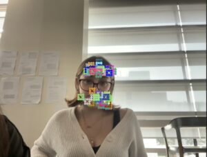
I have always been interested by programs that can locate certain areas of the body or face through advanced technology. Although it is a very critical process and it takes several trials and sample pictures to achieve, its results in a very exciting and rather interactive process.

Symmetry | Free Full-Text | Facial Feature Movements Caused by Various Emotions: Differences According to Sex

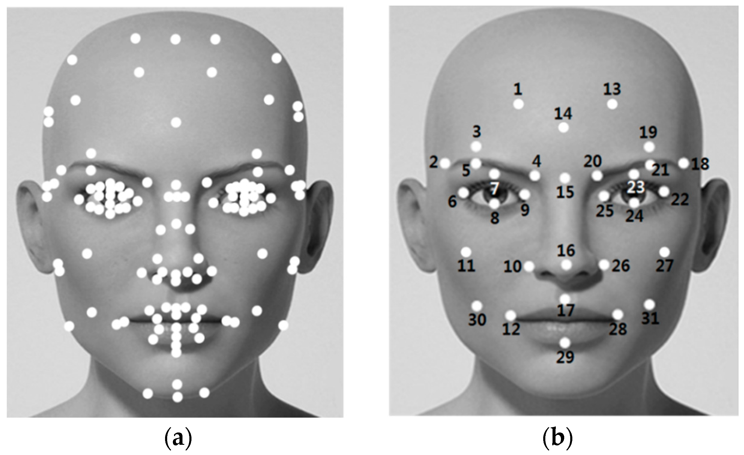
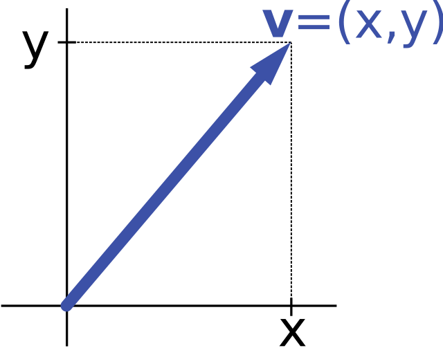
Although this concept is really interesting, what fascinated me even more is just how much we can do with these facial marker. What I found interesting was the ability to track vectors to mimic the facial movements, and to draw those vectors and represent over the camera. As I thought of these changes in the displacement and the x and y values of the vector I wondered how we can visualize this change, and that is when I thought of a simple graph used in physics and maths all the time, a Position vs. Time Graph!

2.3 Position vs. Time Graphs | Texas GatewayVector notation - Wikipedia

Concept:

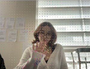
My program aims to use the p5.js library to capture video input, analyze optical flow, and visualize motion through graphical representations with the help of vectors. Mainly visualizing vertical and horizontal changes in the vectors. The flow file deals with detecting motion and optical flow, which are concepts beyond the scope of the class, but with the help of implementations I found online I integrated them in the flow.js file

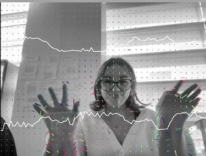
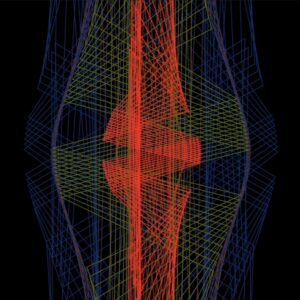
The flow and its arguments returned are then used to draw motion vectors on the canvas, representing vertical and horizontal motion detected. In addition, the program instantiates two instances of the graph class to visualize the left-right (graph on top) and up-down (graph on the bottom) motion over time, creating trailing graphs that represent the history of the patterns. Throughout the draw loop, the motion vectors are modified with Perlin noise to introduce randomness and trigonometry as well.

How it Started:

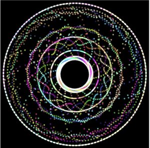
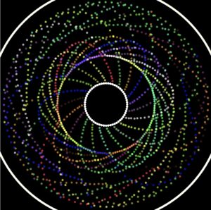
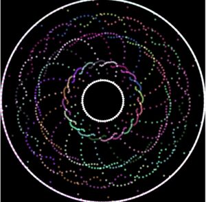
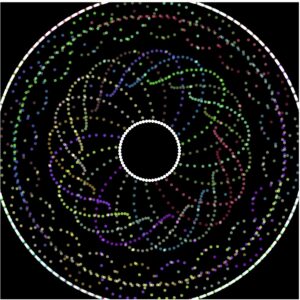
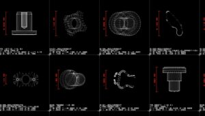
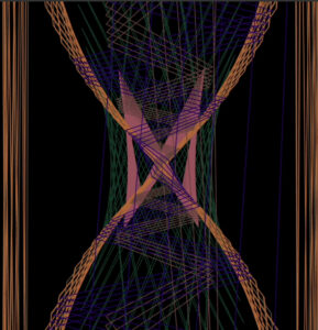
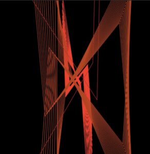
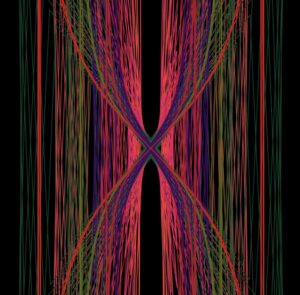
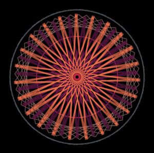
Initially I had a completely different idea in mind. I planned to take several of these quick sketches i implemented and have a program represent how words and actions can make a difference, and my initial sketches are shown bellow:


When looking at the pros and the cons of integrating all these sketches into one, I found that the cons were outweighing the pros. The positives of this idea is that it uses many concepts of the ideas we covered in class, from vectors, fractals, steering forces, perlin noise, particle system, and more.

However the biggest downside of this idea was although it ticked the boxes of integrating the material taught in class, it lacked visual aesthetics. Not only that, but p5.js usually lags and slows down when integrating too many things at once, especially if it includes user interactions.

Initially I took inspiration from the flow field code demonstration we had gone over in class that integrated perlin noise. I then integrated the webcam as my user interaction method. While working with displaying the vectors I went back to the perlin noise integration and decided to add that to the vectors to ensure a smoother transition when the vectors x and y components are changing.

Final Project: Stages

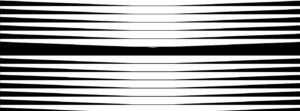
Stage 1: Camera Input 

https://editor.p5js.org/ea2749/full/W9QWMntNK

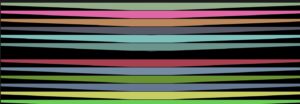
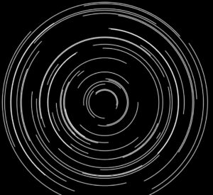
Stage 2: Integrating flow field and Perlin Noise

https://editor.p5js.org/ea2749/full/aTHHs17Mj

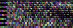
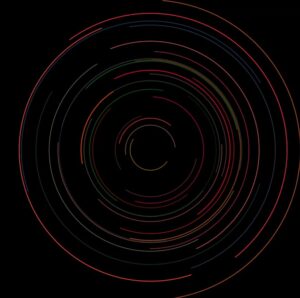
Stage3: RGB dependencies on vector’s x and y

https://editor.p5js.org/ea2749/full/hrdedXJrD

Stage 4: Graphical Representation& Final Tocuches

https://editor.p5js.org/ea2749/full/2-pGvXr8o

Tackling Challenges:

The main challenge I faced was trying to understand the user interaction methods I wanted to use. Since I wanted to explore outside my comfort zone, I had to try new types of user interactions besides the mouse and keyboard, so I decided I wanted to use the webcam

Face marker locations (blue dots) in the Vicon recordings. The markers... | Download Scientific DiagramMarker MPEG-FAP association with the TRACK's reference model. The MPEG... | Download Scientific Diagram

While using the camera, I found ways online in which we can get these facial points, however, translating the returned values of these methods and programs that help us navigate such interactions into arguments I can use similar to our vector implementation in class was difficult. When dealing with user interaction methods like these, we don’t always get values or return types that are flexible to use with any method or class, so modifying, simplifying the code, using chat GPT,  and trials and errors helped.

Snippets of Code:

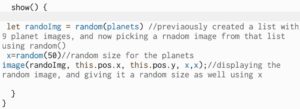
Displaying Vectors and Using them as Arguments:

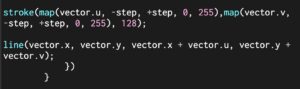
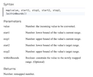
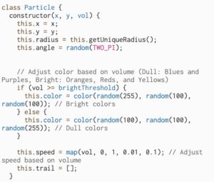
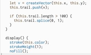
Vectors were represented by lines, taking the x and y values of the vector as arguments for the line. As for the color, we use the map function to take a value from the horizontal/verticle component of the vector and translate it to a value from 0 to 255 so we can use them as our RGB values. Notice how the colors will only change if the vectors horizontal/verticle component changes, meaning the colors change only when movement is detected.
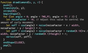
Using Perlin Noise:

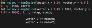
Using perlin noise to achieve a smoother transition between the movement of the vectors and also using the map function to translate the values into smaller values that will make the noise function more seamless and smooth.
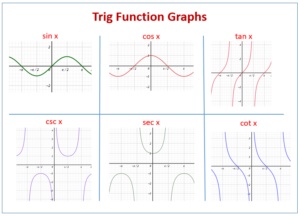
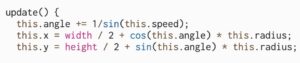
Using Trigonometry:

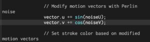
Using trigonometry specifically sin and cosine to limit the incrementing of the vertical and horizontal component of the vector from [-1,1]. This limits our incrementing even more making the transitions even more smooth and seamless.

FINAL Product:

https://editor.p5js.org/ea2749/full/2-pGvXr8o

Reflection and Areas of Improvement:

To conclude this project, and this semester, I really enjoyed the process of developing this project mostly because I got to learn so many concepts of user interaction, and I also was able to integrate concepts taught in class such as vectors, perlin noise, and trigonometry.

Core Principles: Critical Reflection - Center for the Professional Education of Teachers

To further advance this project, I plan to find other ways to make this project more interactive, perhaps creating more sensitivity to motion. Or perhaps having the vectors react differently based on the extent of motion. I also think the project could have been better if I used objects from the physics libraries instead of representing the vectors as lines.
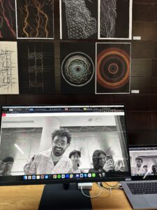
The IM ShowCase:

Coding Assignment Week #11 – Perlin Diamonds& Final Project Idea

Inspiration: 

For this weeks coding assignment, we had to work with the concept of cellular automata to develop dynamic and aesthetically interesting patterns. One thing I find interesting about most patterns developed by cellular automata is that the clusters of objects instantiated always somewhat resemble cells or bee hives or really just any cluster that occurs in a pattern that we see in nature . So for this program, I thought of how I can give this pattern movement, which is why I integrated randomness with color and also added perlin noise.

Nature. Bright Clusters Of A Mountain Ash In Snow. Фотография, картинки, изображения и сток-фотография без роялти. Image 46653805Cell Confluency: Why It Matters and 3 Easy Methods

Progress: 

To better understand the concept I first went over the code demonstrations, and I took inspiration from the Nonrectangular Grids as they resemble a bee hive pattern.

First thing I experimented with is the trig functions, because I remember that with my midterm project that one component that made the most significant and drastic changed was trigonometery and switching around the functions and working with 1/trig functions and more. So that is what I had done above

Added color randomness

For final touches, I used the Perlin noise function to generate smooth variations in the positions.

Final Program:

Ideas for Final Project:

  • Human Body Interaction
  • Sensor tape (Borrow from art center)
  • Seeking/fleeing from  Multiple Targets(Targets being the specific sensors on the sensor tape)

Fleeing/Seeking Objects with Fractal Patterns:

  • Fractal patterns with integration of trig

Scientists discover fractal patterns in a quantum material | MIT News | Massachusetts Institute of Technology

Premium Vector | Abstract fractal patterns and shapes infinite universemysterious psychedelic relaxation pattern dynamic flowing natural forms sacred geometry

Coding Assignment Week #10 – Program+Reading Reflection

Alien Intelligence By Neil Leach: Reflection

In summary, Neil Leach’s lecture at thE FIU School of Architecture mainly revolves around the topics of what is AI, the future of AI, AI image generation, and predictions around the future of AI and architecture. One key concept Leach continues to shed light on is how AI holds this “kind of” intelligence, and it really is not the same as human intelligence at all, but is superior to our capabilities. Leach also brings up how AI could be invisible, and really all around us but we tend to naturally associate AI to physical or tangible things. One thing that leach brings up that I was thinking about before watching the lecture is how terrifying AI can be. Not because it possess capabilities to harm individuals or cause chaos, but more in the sense that it has overly fascinating and shocking capabilities, and I quote Leach’s words “Anything we can do, AI can do better”.

What is AI? Everything to know about artificial intelligence | ZDNET

Coding Assignment: Description 

In this project I mainly use the Matter.js physics engine to create a program  where geometric shapes with random color. The main components consist of two classes: “Boundary” for creating static rectangular boundaries, and “CustomShape” for generating dynamic square objects with random attributes. The Matter.js engine mainly handles collisions and movements. The setup function initializes the canvas and Matter Engine, creating fixed boundaries within the canvas. The draw function continuously updates and displays the boundaries, shapes, and their interactions.

An Introduction to Matter.js

Beginning Sketches:

Final Program:

Reflections and Future improvements:

For this weeks coding assignment, I struggled a bit because I still find that the matter.js library and implementing it is new to me and I definitely need to practice and work on more programs utilizing it.

If I hopefully manage to improve my skills in using the library, since it can create very creative programs that are aesthetically pleasing, I plan to hopefully integrate it in my final project and see how it would work with other methods such as attraction, fleeing, seeking, etc.

Core Principles: Critical Reflection - Center for the Professional  Education of Teachers


Continue reading “Coding Assignment Week #10 – Program+Reading Reflection”

Coding Assignment Week #9 – Confetti System

Inspiration:

When I think of confetti I think of celebrations, and birthdays and the joy and laughter that comes with it! Interestingly, the way confetti moves in air when it is first released from its container is a very sudden and quick movement, which if you arent paying close attention to, you could easily miss. Which is why I began to think of how I can better visualize such confetti, and what would make this movement slow down, so we can visualize this motion and its changes more clearly.

Bright colourful party sparkling party confetti background canvas prints for the wall • canvas prints explode, entertainment, luxury | myloview.com

Concept:

The concept of this program mainly revolves around a simulation of a flock of confetti, which are simple agents that move similarly to confetti with a more limited speed. The main classes are Flock and Boid(confetti). The Flock class manages a list of confetti instances and has methods to simulate the collective behavior of the collection and add more confetti. 

The behavior of the flocking  revolves arounf three main principles/rules: separation, alignment, and cohesion. The flock method in the Boid class calculates forces for each of these principles based on the positions and velocities of neighboring boids/confetti particles. These forces are then applied to the boid’s acceleration, influencing its movement. The update method handles the adding of acceleration to update the boid’s position and velocity. The display method visually represents each boid as a neon-colored dot with a line trace, creating a dynamic simulation.

Bird Brain Maps: Study Explores the Neuroecology of Flocking in Birds | College of Biological Sciences

How to create a boids system (flocking algorithm) - Scripting Support - Developer Forum | Roblox

Program With Comments:
Reflection:

As I concluded this program I began to wonder how I could further advance this program visually, which is when I thought of the methods we learnt about last week and how they can really push this program. For instance, a more dramatic separation steering behavior is particularly suitable for this program, because it serves to keep the confetti from clumping together.

Local separation, alignment and cohesion on the motion of flocking... |  Download Scientific Diagram


Coding Assignment Week #8 – Fleeing Butterflies

Inspiration :

In nature, there are several organisms and species that naturally are attracted to certain scents or colors in other organisms such as plants and animals. And on the contrary, they also flee from certain things. In more scientific terms, this process is also called, escape response.  It is a mechanism by which animals avoid potential predation.

Birds of a feather flock together to confuse potential predators


Concept: 

This program works with a butterfly class, that we instantiate several of and add a fleeing method to it. The class has properties such as position, velocity, acceleration, maximum speed, maximum force, radius, and wing color. The class includes methods for updating the butterfly’s position based on its velocity and acceleration, applying external forces to the butterfly, making the butterfly flee from a specified target (the ellipse in position mouseX MouseY)  if it is within a certain distance, and displaying the butterfly on a canvas using a shape resembling butterfly wings. The butterfly’s appearance is determined by random colors and the shape of its wings is drawn using ellipses.

33 Butterflies aesthetic ideas | butterfly, aesthetic, beautiful butterflies

Program:


https://editor.p5js.org/ea2749/sketches/d3LJADOUE

Midterm Project – Sound-Wave Sculptor

Inspiration:

I find that using your voice to create art can be interpreted in many ways. Several people take their experiences and perhaps even struggles and use art to voice their opinions. So while thinking of this idea of using your voice to make art, I began to wonder whether I can design a program to make generative art by using human voice, literally rather than figuratively…

I was wondering whether similar programs have been built before when I stumbled upon an article by Japanese artist Ryoji Ikeda, known for his innovative and contemporary work in the fields of sound art. His project , cyclo.id, in particular, caught my eye. His program focuses on creating circular patterns by the audio’s phase and amplitude and displaying it graphically. 

However, I felt as if although the black and white combination really allows us the viewer to focus on the patterns, I personally think that a pop of color is much more fun! That when the idea of warm and cool colors came to my mind. I began to wonder, what if I could take the idea of generative audiovisual patterns, and associate this audio and specifically the volume level to cool and warm color shades. Here are a few pictures of contrasting warm and cool colors I looked at to gain inspiration for my color palette. 


Concept:

The SoundWave Constructor is a program that generates an interactive art piece that dynamically responds to audio input from the computer’s microphone every time the program is ran. Every time the user makes noise, the program stores the volume level, and also instantiates a particle every time through the Particle class. 

Interestingly, several of the components/attributes of the particle will directly depend on the volume level. For instance, the color of the particle and its trace will depend on whether the volume recorded at that second by p5 is higher or lower than the Threshold. The color of the instantiated particle would be closer to the warmer colors such as the reds, yellows and oranges when the volume recorded is higher than the threshold and closer to the cooler colors such as the blues, purples and greens when the volume recorded is lower than the threshold.

Other factors that depend on the volume include the speed of orbit and the radius of orbit of the particle, and the same idea applies as well, higher/lower volumes constitute to faster/slower speed and larger/smaller radius respectively. I will explain these methods and their implementations in depth in the Code section of this blog post.

How it Started:

The initial Idea I had in mind was creating almost a digital and audiovisual record player. The way I did that was through creating a very similar particle system and continuously instantiating ellipse particles that also left a trail. Follow along for short descriptions/displays of several programs I tried out before I got to the final program. 

At first, I mainly focused on the instantiation of particles from the particle system. Not focusing on colors, nor speeds, my program lacked a pop of color, but also lacked that generative and creative aspect. Here’s how it looked at that stage:

Next thing I worked on was making sure that based on the volume, the speed of the instantiated particle was determined, and the color as well. Higher volume, faster speed, and brighter colors, lower volume, slower speed, and more dull colors. Snippets of this code and further explanation will be included in the code section. 

Once I got the speed and color covered, I began to wonder how much more can I push the generative aspect of this program? I began to think of this especially because I noticed that the behavior of these particles are very predictable, and that defies the purpose of generative art! Thats when I began to wonder, how can I play around with trigonometric functions and audio input to make the art less predictable. 

I mainly used trig values to computer the vector’s x and y, and also as part of the particles speed. The way I got the sketches bellow was by randomly switching around the trig values, and also experimenting with rational functions to see the different patterns. Here were a few sketches .

Here are a few sketches I got after fully developing the program:

Tackling Challenges: 

The main challenges I faced included editing my code so that it can save an SVG file to be printed on the x, y plotter. At first the SVG would save however it would not open on inkscape. I kept trying various variations in order to get an SVG file that opens on inkscape, but most of them either ran errors or simply did not open. 

After following the exact steps on the powerpoint presentation, and revising the syntax for mouse pressed, in addition to trials and errors, I was able to capture an SVG file that looked exactly like my program, and also captured the several layers of the particles and their trails, which was ideal for the printing.

Other challenges I faced included trying to pick which trig value to use as a parameter for vectors’ x and y values, as well as the angle. Playing around with the different trig values gave me several types of patterns, and each combination of trig functions gave a completely different pattern all of which were generative and looked very interesting. It was very difficult to pick one specific pattern, but I found that the combination I used in my final code was very visually pleasing. 

To better visualize take a look at the various trig function and their graphs over their period:

One more challenge I faced is leaving the trail on the leading particle. I initially made the leading particle an ellipse, however, I reduced the ellipses size by giving it radius of zero in order to create an illusion of an invisible leading particle. To figure out how to leave the trace, I looked into the update method, and also the create vector method, and combined both to store into the trail history list. 

Snippets of Code:

Using Particle System:

The Particle class is responsible for the individual particles. Each particle is created with a unique radius and a random starting angle, which is then manipulated with other trig functions. The color of the particle is determined based on the volume of the microphone input, with brighter colors for higher volumes. The speed of the particle is also adjusted based on the volume. The position of the particle is updated in the update method, and the path is recorded in the trail array. The display method draws the trail and a very small ellipse, which does not show as its meant to lead the trail, at the current position of the particle.

The ParticleSystem class is responsible for handling a collection of particles. In the update method, it calculates the number of particles to add based on the microphone volume and creates new particles at the specified location. If the number of particles is more than a certain threshold, which is 50 particles, older particles are removed. The display method updates and displays each particle in the system.

Managing Path Direction Through Vectors:

 A vector v is created using createVector(this.x, this.y) and it represent the current position of the particle.The vector is then appended to the array this.trail to record the path of the particle. This trail array stores the positions of the particle over time, which later is used to draw the path.The display method of the Particle class uses the this.trail array to draw the path of the particle by connecting the recorded positions using vertex calls, creating a visual trail.

Trigonometric Functions Patterns:

In the update method, the particle’s new x and y coordinates are calculated using trigonometric functions cos and sin. These functions use the this.angle and the particle’s this.radius to get the new position. This.x is calculated as width / 2 + cos(this.angle) * this.radius, which moves the particle horizontally based on the cosine of the angle.this.y is calculated as height / 2 + sin(this.angle) * this.radius, which moves the particle vertically based on the sine of the angle.

FINAL Product:

Note: Please make sure to enable your mic and allow access to run the program using user audio, the link of the program is attached below.

https://editor.p5js.org/ea2749/full/VkTBdCFbK

Plotter Sketches:

Reflection and Areas of Improvement:

Creating this p5 program was a very enlightening and fun journey, I most importantly learned how to take the examples, and concepts learned in class and integrate them with one another to create a program  that makes generative art. What I enjoyed the most was really trying out all the variations of trig functions I could use to make different patterns, because it allowed me to really visualize how big of an impact switching trig functions can have on our parameters which was the speed and angle.


Although I am satisfied with how my program turned out, I really look forward to further advancing this code and improving certain aspects such as working with more complicated trig functions and visualizing other potential patters. Or perhaps having several different types of particles behave is various ways rather than just one particle in a particle system.


Coding Assignment Week #6 – Midterm Project Preperation 2.0

Finalized Concept:

The main idea of my code is using user’s audio input to instantiate objects , which are these orbiting circles. Noise made by the user will instantiate objects of the particle class.  The more noise the user makes, the mic.getlevel function will record that volume, and objects of the particle class will be instantiated. Besides the particle system concept, I decided to also integrate the sin and cosine function that take in the angle as an input, which creates that curved path. The program to play different music/change colors and speeds based on the volume of the user’s audio. For instance: associating higher volumes, that is when mic.getlevel exceeds a certain threshold,  to brighter colors (oranges, yellows, reds), more high pitched music(guitar, bass, drums), and increasing the speed of the particles, while associating lower volumes ,that is when mic.getlevel is below a certain threshold,  to more dull colors (blue, purple, green), more low pitched music(piano, violin, harp), and decreasing the speed of the particles.

Progress from Last Week:

  • Implemented the getVolume and Threshold
  • Implemented the increase/descrease speed based on volume using map function
  • Associated certain colors to volumes by restricting the randomness in RGB values
  • Clearing/splicing elements from the particle system list when list gets too long
  • Implemented a list that stores radii that have already been used so particles instantiated dont overlap


SVG files:

I am currently having trouble downloading the zip files on my laptop, I booked office hours and will try to get help from my peers to hopefully resolve this issue. I was facing issues with the download which is also why I was not able to submit this on time, sorry for the inconvenience.

Program:


Coding Assignment Week #5 – Midterm Project Preperation

Inspiration:

Music Notes Photos, Download The BEST Free Music Notes Stock Photos & HD ImagesCrosley Cruiser Deluxe Vinyl Record Player - Audio Turntables - Walmart.comHow to use Enhance Recording in iOS 14 Voice Memos | AppleInsider


Music and musical notes have always been an interest of mine, and I am specifically intrigued by how different instruments, amplitudes, and volumes work together to make music. I started to think of how these ideas can be visualized through a program, and that when I thought of the audio-generated record player!


Concept:

The main idea of my code is using user’s audio input to instantiate objects these orbiting circles. The more noise the user makes, the mic.getlevel function will record that volume, and objects of the particle class will be instantiated. Besides the particle system concept, I decided to also integrate the sin and cosine function that take in the angle as an input, which creates that curved path. Ideally I plan to also allow the program to play different music/change colors and speeds based on the volume of the user’s audio. For instance: associating higher volumes to brighter colors (oranges, yellows, reds), more high pitched music(guitar, bass, drums), and increasing the speed of the particles, while associating lower volumes to more dull colors (blue, purple, green), more low pitched music(piano, violin, harp), and decreasing the speed of the particles,

Color Psychology: Does It Affect How You Feel?

Sketch:

Clap your hands, or make any noise to start the program.

Note: Make sure to allow access to mic when the pop-up appears

Challenges I may encounter:

Trying to integrate the microphone, and get volume is still really out of my comfort zone, but since the weight of this project is on creativity I am more eager to take the challenge. I feel like I may struggle to identify what volume exactly should be considered high/low pitch in order to make the program’s colors/speeds/audios transition. I think it might help for me to watch videos on youtube, I already began watching a few from the coding train which is how I made progress to the code above. I plan to watch more, and continue to keep making sample sketches.

javascript - Creating a Sound Wave using P5.js - Stack Overflow


Coding Assignment Week #4 – Simple Harmonic Motion Art

Inspiration: 

Ceiling Medallion Stencils - Custom Ceiling Design - Paint Stencils – Modello® Designs

Premium Vector | Circle pattern cnc design vector clip art vector hand drawn stencil element collection


One thing I really enjoyed as a child was making art using the circular stencils, its easy and follows unexpected patterns, yet draws stunning patterns and art! For that reason, I implemented this interactive art making program that works using trig functions (sin and cosine), amplitude and period, and of course the mouse for user interactivity.

Program/Code Explanation:

What I implemented is an interactive sketch that involves a dynamic pattern of 20 ellipses being displayed on a canvas based on sin and cosine functions. The ellipses’ properties are influenced by the position of the mouse, which is what initiates the user interactivity .

 Future Improvements:

As I concluded this project, I began to wonder whether I can integrate randomness to the way the patterns are drawn rather than mouse/user interactivity. I also feel like it would be really cool, although perhaps difficult, to control the movement with other senses rather than touching the mouse board, maybe perhaps integrating one’s voice and controlling the movement with high/low pitch voice as a form of interactivity.


Week 3 Assignment – Elyazia Abbas

Concept and Inspiration:

Our task this week was to use invisible attractors and visible movers to create a pattern from the objects moving around attractors. I immediately imaged planets and orbital motion when thinking of this concept. Although the attractor in this case would be the sun, which is not invisible, in my implementation, I used a thin outline of a white circle just for reference and to easily track the orbital motion.

Something new that I was interested in while writing this program, was randomly picking a randomly sized image of a planet from a list to display in orbit, which I will further explain later. Every time the program is started the attractor is placed on a random spot on the screen through using random coordinates, and the user can use the mouse in order to drag the attractor top different spots, and the movers will continue to move around the allocated spot.

Code Snippet:

In the sketch file I created a list of 8 images of planets in our galaxy, and used this new function I learned by watching this video on youtube on how to randomly generate images on p5 https://www.youtube.com/watch?v=hxjEl-pun7o. I also made sure to randomly size the images as well to make it look more natural.

Trial Sketches before the final Product:

These were just a few trials to experiment before finishing my program: