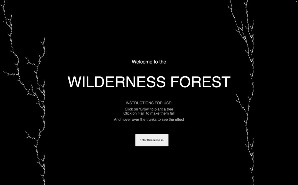
THE FINAL SKETCH
Click on the button to enter the simulation!
Here is the full p5.js code: https://editor.p5js.org/shreyagoel81601/sketches/Y6gK7f1Iz
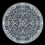
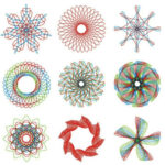
MY DESIGN GALLERY
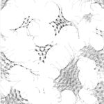
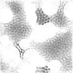
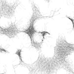
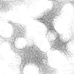
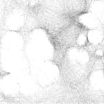
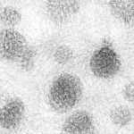
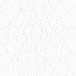
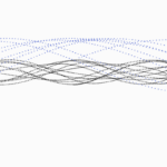
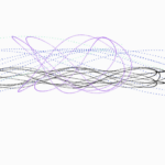
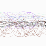
Below are the various different outputs I got from my above sketch:
INSPIRATION, CONCEPT & ARTISTIC VISION
We studied fractals in class and I was specially fascinated by it. Just a recursive function with some property to it, a set of rules, and one can make such interesting patterns! I wanted to delve deeper and explore the field of fractals further for my final project, using it in a creative way to design intricate and mesmerising patterns that one wants to keep looking at.
Fractals are an important branch in mathematics and its recursive properties (i.e. self-similarity) are of interest in many fields. They are used in applied mathematics for modelling a variety of phenomena from physical objects to the behavior of the stock market. The concept of the fractal has also given rise to a new system of geometry crucial in physical chemistry, physiology, and fluid mechanics. But what if fractals were not limited to these set of equations and properties jargon to many but presented in a visually appealing way to the wider audience? To really show how broad and fascinating the field of math is and how it can be used to create art. That is what I set out my final project to be. To really curate a design or simulation which evolves over a period of time just based of fractal properties we study in math. More about fractals: source1, source2, source3.
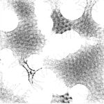
Mathematical fractals:

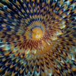
Fractals in nature:

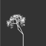
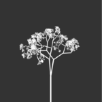
Out of all the fractals that exist out there, I was most intrigued by the ones that appear in leaves and trees and hence decided to re-create those using the idea of recursion with some of the known fractal equations and set of rules. However, the focus was not only on generating naturally occurring fractal patterns – the trees, but also putting them together in a creative way, artistically curating it into some sort of a generative algorithm or simulation, evolving over period of time with which the users could interact and play with. I proceeded with simulating a forest scenario – where users can plant a tree, make them fall, or have them sway upon their hover interaction, as if one is shaking their trunk!
THE PROCESS, TECHNICAL DESIGN & IMPLEMENTATION
I started with first reading thoroughly upon fractals and informing myself about those so I could choose which kind of fractals to go with, how to code them, what properties to use, etc. I had known what fractals are, but now, I was interested in knowing their origin, their nature, how it gives rise to certain forms and patterns, and so on. I went down a rabbit hole studying fractals, to the extent that I started proving its properties xD. It was very enriching!
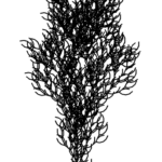
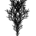
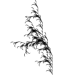
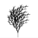
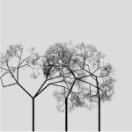
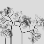
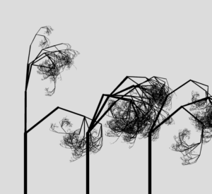
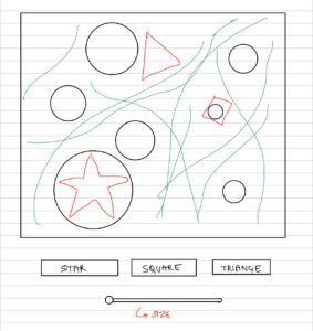
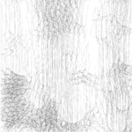
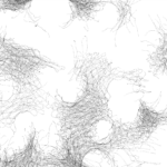
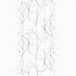
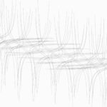
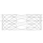
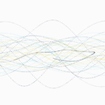
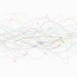
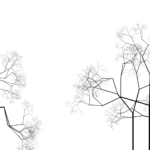
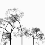
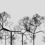
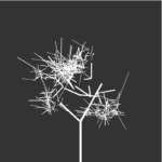
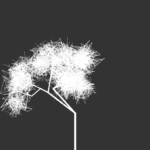
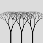
My project uses 2 kinds of fractals – the L-system (for the instructions/home page), and stochastic branching fractals for the main wilderness forest part. I started with what we had in class first, the recursive way of building the stochastic trees and played with its design to create a forest like system. See below my initial sketch:
// in setup()
  fractalTree(width/4, height, length*1.2, 8);
  fractalTree(width/8, height, length*0.5, 3);
  fractalTree(width/2, height, length*1.5, 7);
  fractalTree(width/8*7, height, length*0.5, 3);
  fractalTree(width/4*3, height, length*0.7, 5);

// the recursive function
function fractalTree(x, y, len, weight) {
  push();
  if (len >= 2) {
    //draw the first line
    strokeWeight(weight);
    translate(x, y);
    line(0, 0, 0, -len);
    translate(0, -len);
    weight *= sweight;
    strokeWeight(weight);
    weight *= sweight;

    let num = int(random(4));
    for(let i = 0; i <= num; i++) {
      push();
      let theta = random(-PI/2, PI/2);
      rotate(theta);
      fractalTree(0, 0, len*0.67, weight);
      pop();
    }
  }
  pop();
}
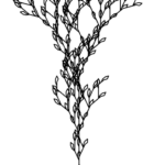
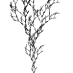
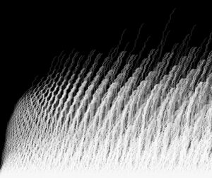
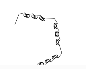
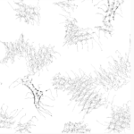
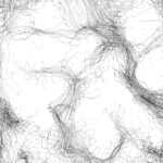
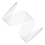
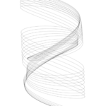
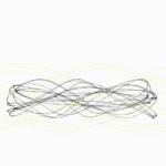
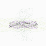
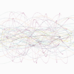
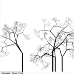
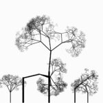
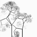
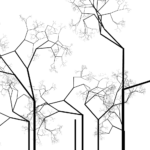
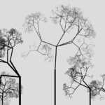
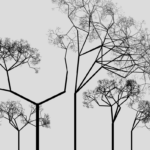
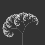
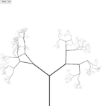
Above is a static version, it has no movement or user interaction yet. Next I tried exploring L-systems. Here is the sketch for that:
// in setup()
  let ruleset = {
    F: "F[F]-F+F[--F]+F-F",
  };
  lsystem = new LSystem("F-F-F-F", ruleset);
  turtle = new Turtle(4, 0.3);

  for (let i = 0; i < 4; i++) {
    lsystem.generate();
  }

// in draw()
  translate(width / 2, height);

  let angle = map(mouseX, 0, width, -0.3, 0.3);
  let h = map(mouseY, height, 0, 0, 8);
  turtle = new Turtle(h, angle);

  turtle.render(lsystem.sentence);
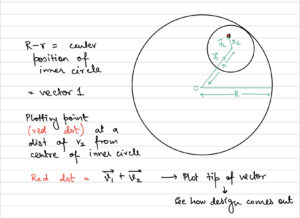
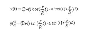
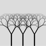
After playing around and educating myself of the different ways one can use fractals to simulate trees and forest situations, it was time to curate the performance. I wanted to have the trees not be static, but grow slowly, and also sway as if wind is blowing. For this, it was necessary that I move away from the recursive way of coding because a recursive function just draws the tree once, done, it stores no property taht one can alter to later on play with it and achieve the results I intended to create. Hence, I transitioned to an OOP way inspired by Coding Train.
class Branch {

  constructor(begin, end, strokew) {
    this.begin = begin;
    this.end = end;
    this.finished = false;
    this.strokew = strokew;
    this.speed = random(4,12);
  }

  branchA() {
    let dir = p5.Vector.sub(this.end, this.begin);
    dir.rotate(random(-PI/2, PI/2));
    // dir.rotate(PI / 6 + dtheta);
    dir.mult(0.67);
    let newEnd = p5.Vector.add(this.end, dir);
    let b = new Branch(this.end, newEnd, this.strokew*0.8*0.8);
    return b;
  }

  branchB() {
    let dir = p5.Vector.sub(this.end, this.begin);
    dir.rotate(random(-PI/2, PI/2));
    dir.mult(0.67);
    let newEnd = p5.Vector.add(this.end, dir);
    let b = new Branch(this.end, newEnd, this.strokew*0.8*0.8);
    return b;
  }
}
let forest = [];
let numTrees = -1;

genButton = createButton("Grow");
genButton.mousePressed(createNewTree);

function createNewTree() {
  let len = randomGaussian(height*0.25, 20);
  let x = random(10, width-10);
  let w = map(len, 0, height/2, 2, 12);

  let a = createVector(x, height);
  let b = createVector(x, height - len);
  let root = new Branch(a, b, w);

  let tree = []
  tree[0] = root;
  forest.push(tree);

  numTrees++;
  count = 0;

  generateBool = true;
}

function generate() {
  let tree = forest[numTrees];

  if (count < 12) {
    for (let i = tree.length - 1; i >= 0; i--) {
      if (!tree[i].finished) {
        tree.push(tree[i].branchA());
        tree.push(tree[i].branchB());
      }
      tree[i].finished = true;
    }
    count++;
  }
  else {
    generateBool = false;
  }
}

function draw() {
  if (generateBool) {
    generate();
  }
}
However, this was not easy or straightforward. I ran into many challenges.
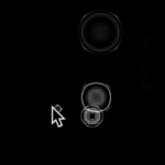
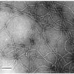
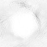
BLOOPERS
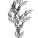
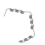
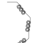
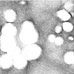
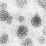
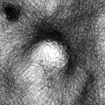
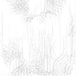
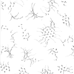
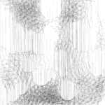
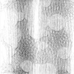
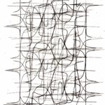
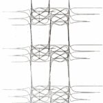
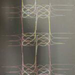
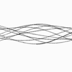
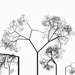
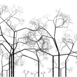
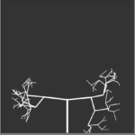
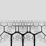
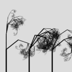
To implement the sway feature, I decided to have the trees jitter upon mouse hover, to create the effect of a user shaking the tree. The basic idea for this was to change the angle of each branch for it to create a sway effect, but that lead to disintegrating the tree (see below).
This happens because when creating the tree, each branch starts from the end of previous branch, and when I rotate, the end point of previous branch moves but not the starting point of the new branch. The way I fixed this is by altering the end points for sway and not the angle and then redrawing the next branches based on this new end point.
if (mouseX < width && mouseX > 0 && mouseY < height && mouseY > 25) {
      for (let j = 0; j < forest.length; j++) {
        let tree = forest[j];
        if (abs(mouseX - tree[0].begin.x) < range){
          for (let i = 1; i < tree.length; i++) {
            tree[i].jitter();
          }
        }
      }
    }
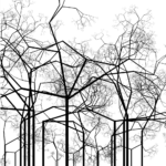
Another issue I faced was nailing how many branches the tree should have. Because otherwise it was getting too heavy for the program to run and my laptop kept on crashing. If it was too little branches, then it would not look like a tree, or real, and would defeat the purpose of the whole model.
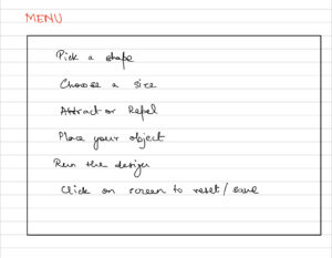
INSTRUCTIONS PAGE
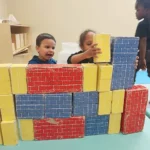
THE PROCESS PHOTOS

IM SHOWCASE PRESENTATION
My project was exhibited at the Interactive Media End of Semester Showcase at New York University Abu Dhabi where it was interacted with by many people, not just students, but faculty, staff, dean from all majors.