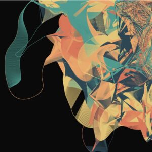
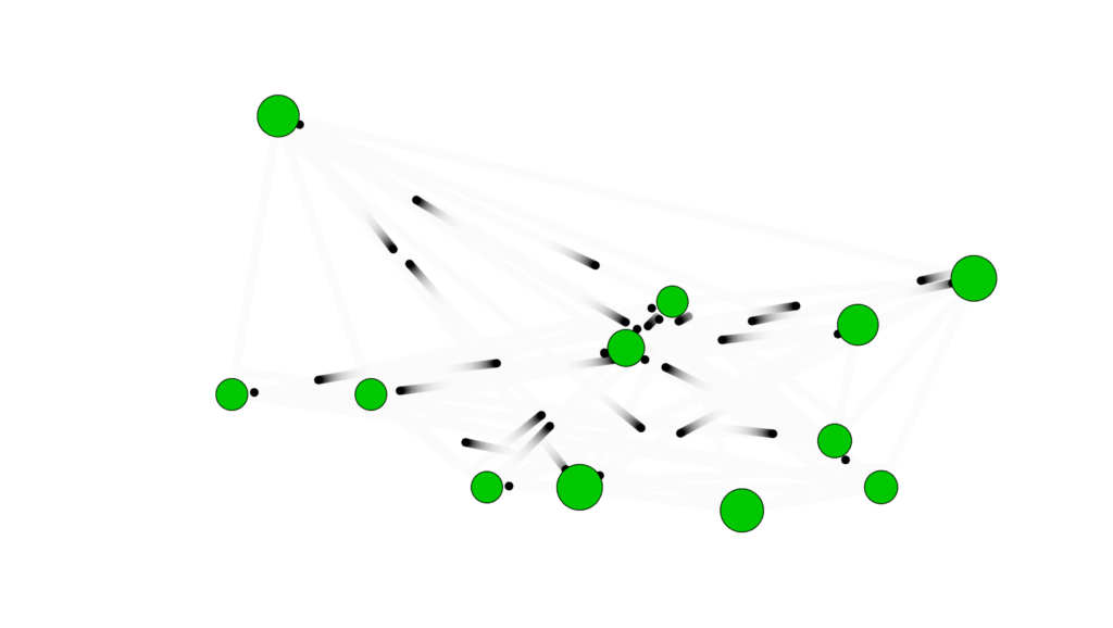
For the midterm, I created a generative art system that explores the intersection of networks and organic motion. The core concept is artificial life simulation inspired by Craig Reynolds’ Boids, but also using lines between nodes as in Network Theory to generate unique paintbrush patterns.
The design goal was to make a system that feels alive rather than programmed. Rather than directly drawing static shapes, I implemented a set of biologically inspired rules such as, movement, proximity-based interactions, growth, and reproduction, allowing the artwork to emerge from these behaviors over time. The result is a visually rich, evolving network that evokes mycelial-network-like pathways, flocking organisms, and orbital motion depending on the selected mode.
The system also includes interactive features that allow the user to manipulate and explore the simulation in real-time:
Movement Modes: Wander, Flock, and Orbit, toggled with M, creating different emergent behaviors.
Color Palettes: Cycle through multiple palettes with C to alter the visual mood.
Growth Control: Nodes reproduce over time, with growth rate adjustable via a slider.
Movement Parameters: Sliders for speed, steering strength, and connection distance allow nuanced control over node behavior.
Mouse Interaction: Click to attract all nodes toward the cursor; press R to repel them.
Fullscreen and Export: Press F to toggle fullscreen, and S to save a PNG snapshot of the current artwork.
Implementation Details
Nodes Behavior:
Wander Mode: Nodes move using Perlin noise to simulate organic wandering.
Flock Mode: Nodes align and cohere with nearby nodes, creating emergent flocking patterns.
Orbit Mode: Nodes orbit around the canvas center with circular movement.
Mouse Influence: Nodes respond to attraction or repulsion forces for interactivity.
if (organisms.length < 400 && frameCount % growthSlider.value() === 0) {
  let parent = random(organisms);
  organisms.push(
    new BioNode(
      parent.pos.x + random(-20, 20),
      parent.pos.y + random(-20, 20)
    )
  );
}
I made it so that the number of organisms in the sketch grows to 400 (capped so the sketch doesn’t lag) at a rate determined by the user using the slider
Midterm Progress Milestone
At this point I was facing a problem where, for some reason, all the nodes would cluster at the top right corner, which left huge parts of the canvas uncovered. I discussed with professor Jack that it would probably be a good idea to allow the user to influence the sketch with the mouse to get better patterns, which is what I did below.
wander() {
    let n = noise(this.pos.x * 0.01, this.pos.y * 0.01, frameCount * 0.01);
    let angle = map(n, 0, 1, 0, TWO_PI * 2);
    let steer = p5.Vector.fromAngle(angle).mult(steerSlider.value());
    this.applyForce(steer);
  }
mouseInfluence() {
  if (mouseIsPressed) {
    let mouse = createVector(mouseX, mouseY);
    let dir = p5.Vector.sub(mouse, this.pos);
    dir.normalize();
    let strength = repelActive ? -0.3 : 0.3;
    this.applyForce(dir.mult(strength));
  }
}
This is how I made the nodes feel alive. These snippets show how I used noise to smoothly randomize movement and steering, but also allow for the user to intervene with external forces to influence the final piece.
for (let i = organisms.length - 1; i >= 0; i--) {
  let o = organisms[i];
  o.update();
  o.display();

  for (let j = i - 1; j >= 0; j--) {
    let other = organisms[j];
    let d = dist(o.pos.x, o.pos.y, other.pos.x, other.pos.y);

    if (d < connectSlider.value()) {
      stroke(o.color, map(d, 0, connectSlider.value(), 100, 0));
      strokeWeight(0.5);
      line(o.pos.x, o.pos.y, other.pos.x, other.pos.y);
    }
  }
}
Because I wanted to try Node-to-Node connections that I saw from my Computer Science classes, I used this nested loop to draw a line between nodes that are a certain distance from each other, depending on the user’s choice, which resulted interesting paintbrush patterns.
orbit() {
  let center = createVector(width / 2, height / 2);
  let dir = p5.Vector.sub(center, this.pos);
  let tangent = createVector(-dir.y, dir.x); // perpendicular to center vector
  tangent.setMag(steerSlider.value());
  this.applyForce(tangent);
}
This is the function the sketch switches to as one of the modes available, which I learned from The Nature of Code book. Since orbit is just a force pulling towards the center, you simply need to subtract the position vector and the center vector to get the direction of the force you need to apply.
The interactive simulation provides an engaging experience where users can explore emergent behaviors visually and through direct manipulation. Observing how small changes in parameters affect the system fosters a sense of discovery.
Future Improvements:
Smoother transitions between modes.
Adjustable node size and trail persistence for more visual variety.
Biological growth patterns, flocking birds, and orbital mechanics.
Creative coding projects on interactive generative art platforms.
AI Disclosure: I, of course, used AI to help me better understand and debug the complex parts of the code, especially flocking. I also asked ChatGPT to suggest the color palettes that the user can cycle between by clicking c since I am not very good at choosing colors. ChatGPT also did the html parts such as the sliders, labels, as well as the fullscreen feature.
As crazy as it sounds, a big inspiration of this sketch is a song by a not very well known band called fairtrade narcotics. Especially the part that starts around 4:10 , as well this video: Instagram
To toggle modes, press space to change to Galaxy and press Enter to change to Membrane
GALACTIC is an interactive particle system built around a single mechanic: pressure. Pressure from the mouse, pressure of formation, and pressure of, holding it together. This sketch is built around the state of mind I had when I first discovered the song in 2022. I played it on repeat during very dark times and it was mending my soul. After every successful moment I had at that time, during my college application period, I would play that specific part of the song and it would lift me to galactic levels. The sketch has 3 modes, the charging modes resembles when I put in a lot of effort into something and eventually it works out which is resembled by the explosion. The second state is illustrates discipline by forming the particles into a galaxy. The last is Membrane which represents warmth and support from all my loved ones.
Before writing a single line, I sketched the architecture on paper. The system has three major layers of responsibility: the global state (are we holding? are we exploding? what’s the charge level?), the particle population (a pool of objects that each manage their own physics), and the vfx (trails, embers, glow pulses, which are short-lived visual elements that don’t need the full particle class). I accumulated my notes and compiled them into a beautiful psuedocode that I can follow, this is me abusing what I learned taking Data Structures and honestly desgining the system beforehand works for me really well
please check the pdf for the psuedcode because there’s this ANNOYING issue that no matter whats the scale of the screenshot I am uploading its always so blurry and small.
I also want to disclose that AI helped me with many mathematical sections within this sketch, I wouldn’t be able to understand the math or get around it on my own I think. But I promise my usage is not excessive or dependent and I actually use it to learn haha
Anyway, I started writing attributes for the particle class and oh boy they added up QUICKLY. Here’s a snippet. I tried assigning random values manually but it was very very hard to find the sweet spot for everything so I used some help from AI to assign the proper values to those attributes and I tweaked them a little bit and got really good results.
A useful frame for interactive generative art is the state machine. This sketch has three primary states that produce visually distinct experiences, and the transitions between them are where most of the design work happened.
Idle state: No mouse interaction. 80 particles drift across the canvas on Perlin noise. Each particle has its own noise offset, frequency, and speed. The result is slow, organic, slightly hypnotic. The palette sits in the 228-288 HSB hue range (blue through violet) and particles breathe gently at a rate of 2 cycles per second. This is the sketch’s resting face, and it needs to be beautiful enough to watch on its own.
Charging state: Mouse held. New particles spawn at the edge of the screen and get pulled toward the cursor which acts as an attractor. Spawn rate accelerates from 1/frame to 18/frame as charge approaches maximum. The vortex arms appear past 8% charge: three logarithmic spirals that rotate faster as charge builds, drawn with beginShape()/vertex() and per-vertex stroke colors that fade toward the outer edge. The glow orb grows around the cursor. Screen rumble starts at 60% charge. Particles near the cursor compress and brighten. The hue of nearby particles shifts toward 305, a hot magenta-violet. Every visual element does the same narrative work: energy is accumulating.
Explosion state: Mouse released. This is tiered across four discrete levels (0 through 3) based on charge thresholds at 0.25, 0.55, and 0.85. Tier 0 is a gentle push. Tier 3 is a white-flash, screen-shake, 800-pixel-radius detonation that spawns up to 70 child particles from split candidates nearest the blast origin. Each particle in blast range gets a force vector calculated from distance falloff (pow(1 - d/blastRadius, 2)), a random rotation drift, and a behavior assignment weighted by proximity to center and charge level. The explosion duration scales with charge, from 1.4 seconds to 4 seconds. The slowdown at high charge gives full-tier explosions a cinematic quality: the cloud expands, holds, then dissipates.
The variation space this produces is wide. A quick series of light taps creates a dotted constellation. Holding in one place while moving slightly creates smeared, comet-like trails. A patient full charge, held long enough to feel the rumble, produces a different kind of satisfaction.
the scariest things about this project were two things braided together: performance under additive blending with 700+ particles, and making the multi-behavior explosion feel coherent rather than random.
Additive blending (blendMode(ADD)) is visually spectacular. Overlapping particles bloom into white rather than muddy brown. The cost is real though: each ellipse composites against everything underneath it. With three ellipses per particle (the outer glow halo, the mid-glow body, and the bright core), plus trail objects, plus embers, a naive implementation at 700 particles hits framerate problems fast. The risk was a beautiful system running at 20fps. I ran many optimization processes but then I migrated to VS code which was MUCH smoother but I don’t know how smart that is going to be because in the end I’m gonna have to embed the sketch in p5.js web editor so it wouldn’t make sense or a difference that it runs smoothy on my device but its laggy on the website.
For the behavior system, the risk was that five different particle behaviors during explosion would read as a mess of conflicting physics. To test this, I implemented behaviors one at a time and ran the explosion at full charge with only that behavior active, watching whether each produced a readable visual signature. BEHAVE_COMET needed the highest speed and the lowest drag (0.99 vs the standard 0.93-0.97) to produce visible streaks. BEHAVE_BOOMERANG needed the timer offset: if the return force kicked in immediately, particles just wobbled. They needed to actually leave the origin first. BEHAVE_FLUTTER was the most unpredictable and required the dampening multiplier (vx *= 0.985) to prevent runaway acceleration from the oscillating force.
The assignBehavior() method’s probability table weights behavior by charge level and proximity to blast center. Close-in particles at high charge get COMET and SPIRAL; far particles get RADIAL and FLUTTER. This creates a natural visual structure: a dense bright core of fast-moving comets surrounded by a slowly oscillating outer cloud. The explosion has a center and a periphery, which reads as physically plausible even though the physics are entirely invented.
But there comes another problem. I don’t like the black background so I decided to create a galaxy background. I had a rough idea how to make it but I had to do some research.
Guess what, all of those links were useless. I found nothing of help but I didn’t want to give up. so I found this reddit post and I found this page and I follwed the principles and methods in the article to create something cool.
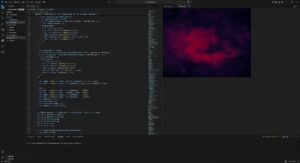
I tried to upload the gif of the animated image but I got this error so I will just upload a screenshot unfortunately.
This is a wall a ran into. No matter what I did with the background, it either looked ugly or became very laggy. So I went with the vibe that space by nature is void and light in it is absent, black is the absence of light. Therefore, the background is black. I feel like a good skill of being an artist is to convince people that your approach makes sense when you’re forced to stick with it.
Then I moved to implementing the galaxy.
The galaxy implementation started with a question I couldn’t immediately answer: how do you turn drifting particles into something that looks like a spiral galaxy without teleporting them there? My first instinct was to assign each particle a slot on a pre-calculated spiral arm and pull it toward that slot. I wrote assignGalaxyTargets(), sorted particles by their angle from center, matched them to sorted target positions, and felt pretty good about it.
function assignGalaxyTargets() {
  let n = particles.length;

  // build target list at fc = 0 (static, for assignment geometry only)
  let targets = [];
  for (let j = 0; j < n; j++) {
    let gi  = j * (GALAXY_TOTAL / n);
    let pos = galaxyOuterPos(gi, 0);
    targets.push({ gi, x: pos.x, y: pos.y,
                   ang: atan2(pos.y - galaxyCY, pos.x - galaxyCX) });
  }

  // sort particles by current angle from galaxy center
  let sortedP = particles
    .map(p => ({ p, ang: atan2(p.y - galaxyCY, p.x - galaxyCX) }))
    .sort((a, b) => a.ang - b.ang);

  // sort targets by their angle
  targets.sort((a, b) => a.ang - b.ang);

  // assign in matched order → minimal travel distance
  for (let j = 0; j < n; j++) {
    sortedP[j].p.galaxyI = targets[j].gi;
  }

  galaxyAssigned = true;
}
I lied. It looked awful. Particles on the right side of the canvas were getting assigned to slots on the left and crossing the entire screen to get there. The transition looked like someone had scrambled an egg.
The fix was to delete almost all of that code. Instead of pulling particles toward external target positions, I read each particle’s current position every frame, converted it to polar coordinates relative to the galaxy center, and applied two forces directly: a tangential force that spins it into orbit, and a very weak radial spring that nudges it back if it drifts too far inward or outward. Inner particles orbit faster because the tangential speed coefficient scales inversely with radius. Nobody crosses the canvas. Every particle just starts rotating from wherever it already is.
The glow for galaxy mode uses the same concentric stroke circle method from a reference I found: loop from d=0 to d=width, stroke each circle with brightness mapped from high to zero outward. The alpha uses a power curve so it falls off quickly at the edges. The trick is running galaxyGlowT on a separate lerp from galaxyT. The particles start moving into orbit immediately when you press Space, but the ambient halo breathes in much slower, at 0.0035 per frame vs 0.018 for the particle forces. You get the orbital motion first, then the light catches up.
The galaxy center follows wherever you release the mouse. This is made so the galaxy forms where the explosion happens so the particles wrap around the galaxy center in a much more neat way instead of always having the galaxy in the center.
One line in mouseReleased():
galaxyCX = smoothX; galaxyCY = smoothY;
like honestly look how cool this looks now
The third mode came from a reference sketch by professor Jack that drew 1024 noise-driven circles around a fixed ring. Each circle’s radius came from Perlin noise sampled at a position that loops seamlessly around the ring’s circumference without a visible seam, the 999 + cos(angle)*0.5 trick. The output looks like a breathing cell membrane or a pulsar cross-section.
My first implementation was a direct port: 1024 fixed positions on the ring, circles drawn at each one. It worked but the blob had zero relationship to the particles underneath it. It just floated on top like a decal. Press Enter, blob appears. Press Enter again, blob disappears. The particles had nothing to do with any of it.
The version that actually felt right throws out the fixed ring entirely. Instead of iterating 1024 pre-calculated positions, drawMorphOverlay() iterates over the particle array. Each particle draws one circle centered at its own x, y. The noise seed comes from the particle’s live angle relative to morphCX/CY, so each particle carries a stable but slowly shifting petal radius with it as it moves.
let ang = atan2(p.y - morphCY, p.x - morphCX);
let nX  = 999 + cos(ang) * 0.5 + cos(lp * TWO_PI) * 0.5;
let nY  = 999 + sin(ang) * 0.5 + sin(lp * TWO_PI) * 0.5;
let r   = map(noise(nX, nY, 555), 0, 1, height / 18, height / 2.2);
The rendered circle size scales by mt * p.life * proximity. Proximity is how close the particle sits to the ring. Particles clustered at the ring draw full circles. Particles still traveling inward draw small faint ones. When you activate morph mode, the blob coalesces as particles converge. When you deactivate it, the blob tears apart as particles scatter outward, circles traveling with them. The disintegration happens at the particle level, not as a fading overlay.
The core glow stopped rendering at a fixed point too. It now computes the centroid of all particles within 2x the ring radius and renders there. The glow radius scales by count / particles.length, so a sparse ring is dim and a dense ring is bright. The light follows the mass.
Originally I had Space and Enter both cycling through modes in sequence: bio to galaxy to membrane and back. That made no sense for how I actually wanted to use it. Space now toggles bio and galaxy. Enter toggles bio and membrane. If you’re in galaxy and press Enter, galaxyT starts lerping back to zero while morphT starts lerping toward one simultaneously. The cross-fade between two non-bio modes works automatically because both lerps run every frame regardless of which mode is active.
morphAssigned = false triggers the angle re-sort on the next frame, which maps current particle positions to evenly spaced ring angles in angular order. Same fix as the galaxy crossing problem: sort particles by angle from center, sort targets by angle, zip them in order. Nobody crosses the ring.
The sketch now has three fully functional modes with smooth bidirectional transitions. The galaxy holds its own as a visual. The membrane is the most satisfying of the three to toggle in and out of because the disintegration is legible. You can watch individual particles drag pieces of the blob away as they scatter.
I still haven’t solved the performance question on lower-end hardware. The membrane mode in particular runs 80 draw calls per particle at full opacity in additive blending, which is not nothing. My next steps are profiling this properly and figuring out whether the p5 web editor deployment is going to survive it. I’m cautiously optimistic but I’ve been cautiously optimistic before.
I faced many challenges throughout this project. I will list a couple below.
The trails of the particles
The explosion not being strong enough
The behavior of pulling particles
Performance issues
The behavior of particles explosion
The Texture of galaxy (scrapped idea)
and honestly I could go on for days.
The thing that worked the best for me is that I started very early and made a lot of progress early so I had time to play around with ideas. Like the galaxy texture idea for example from the last post, I had time to implement it and also scrap it because of performance issues. I also tried to write some shader code but honestly that went horribly and I didn’t want to learn all of that because the risk margin was high. Say I did learn it and spend days trying to perfect it and end up scrapping the idea. I also didn’t want to generate the whole shaders thing with AI, I actually wanted to at least undestand whats going on.
The most prominent issue was how the prints were going to look like as I didn’t know how to beautifully integrate trails as they looked very odd. I played around with the transparency of the background with many values until I got the sweet spot. My initial 3 modes were attract, condense, and explode but that wouldn’t be conveyed well with the prints so I switched to the modes we have right now.
Reflection
Honestly the user experience is in a better place than I expected it to be at this stage. The core loop, hold to charge, release to detonate, turned out to be one of those interactions that people understand immediately without any instructions, bur I can’t say the same about pressing Enter and Space to toggle around between modes haha. I’ve watched a few people pick it up cold and within thirty seconds they’re already testing how long they can hold before releasing. That’s a good sign. When an interaction teaches itself that quickly, you’ve probably found something worth keeping.
The three modes add a layer of depth that I wasn’t sure would land. Galaxy mode feels the most coherent because the visual logic is obvious: particles orbit a center, a halo breathes outward, the whole thing rotates slowly. Membrane mode is more abstract and I think some people will find it confusing on first contact. The blob emerging from particle convergence reads as intentional once you’ve seen it a few times, but the first time it happens it might just look like a bug. That’s a documentation problem as much as a design problem. A very subtle UI hint, maybe a faint key label in the corner, might do enough work there without breaking the aesthetic.
The transition speeds feel right in galaxy and a little slow in membrane. When you press Enter to leave membrane mode, the blob takes long enough to dissolve that it starts feeling like lag rather than a designed dissolve. I want to tighten the MORPH_LERP value and see if a slightly faster exit reads better while keeping the entrance speed the same. Entering slow, leaving fast, might be the right rhythm for that mode.
Performance is the thing I’m least settled about. On my machine in VS Code the sketch runs clean. The membrane mode specifically concerns me because it runs one draw call per particle per frame in additive blending, and additive blending is expensive in ways that only become obvious at 600 particles so it’s a little bit slower there.
The one thing I genuinely would love to add is audio. Not full sound design, something minimal. A low frequency hum that rises in pitch as charge builds, a short percussive hit on release scaled to the explosion tier. The sketch is very silent right now and I think sound would close a gap in the experience that visuals alone can’t. The charge accumulation in particular has this tension that wants a corresponding audio texture.
The naming situation I mentioned at the start, Melancholic Bioluminescence sounding like a Spotify playlist, has not resolved itself. If anything the addition of galaxy mode and the membrane makes the name less accurate. The name now is GALACTIC
Also yes, AI helped with a lot of the math again. The Keplerian orbital speed scaling, the seamless noise ring sampling, the proximity weighting in the blob. I understand what all of it does now though, which I count as a win. I use AI not do my work, but as a tool that helps me get to what I want as a mentor. I think I am very satisified with this output as I built the architecture, I build the algorithms, I designed everything beforehand and when things felt stuck I used AI as my mentor. I think the section where I used AI the most is filling in a lot of values to for things cus I couldn’t get values that felt nice. Here’s an example below.
For my midterm generative art system, I am developing three different design directions. This post focuses on Design 1, which explores Islamic geometric structure through sinusoidal motion.
This design is built around a 10-point star (decagram) arranged in a staggered grid. Instead of treating the geometry as static ornament, I animate it using a sine wave so each star opens and closes over time.
The goal is to reinterpret Islamic geometry in a contemporary, computational way. I’m not copying historical patterns directly. I’m rebuilding their mathematical logic and making them dynamic.
Core System
Each star is constructed using polar coordinates and radial symmetry. The opening movement is controlled by a sine wave:
const open01 = 0.5 + 0.5 * sin(t * 1.8 + phase);
Each grid cell has a slightly different phase offset, so the stars don’t all open at once. This creates a ripple across the surface instead of uniform motion.
I also applied easing to soften the movement so it feels less mechanical and more architectural.
The system integrates:
Trigonometry and polar coordinates
Grid logic with staggered rows
Sinusoidal animation
Easing functions
Interactive controls (pause and save)
Pressing space pauses the animation. Pressing “S” exports a high resolution frame, which allows me to capture specific moments for print.
Visual States
Although this is one generative system, it produces multiple distinct visual states:
Fully closed stars: dense and compact
Mid-open stars: balanced and structured
Fully expanded stars: light and porous
Ripple states: different areas opening at different times
These states will help me select compositions for printing.
Challenges and Next Steps
The main challenge has been controlling the amount of spread when the stars open. Too much expansion causes the geometry to lose its structural clarity. Finding that balance has been key.
Moving forward, I plan to:
Refine line weight variations
Experiment with subtle color variations
Test alternate grid densities
Develop Design 2 and Design 3 as distinct explorations
This first design establishes the structural and mathematical foundation of the project. The next two designs will push the system in different conceptual and visual directions.
At home in Dubai there are many palm trees around where I live. Since I was young I’ve always noticed birds travelling between trees and staying at some trees for a short while only to move again later. I always found their movement very calming so I wanted to replicate this in code and hopefully evoke the same emotions.
Core Concept and Design
The sketch simulates a flock of birds moving between trees. Trees are placed using the noise function where at the highest points in the noise function a tree is placed. Birds spawn at trees, fly toward a randomly chosen tree, and upon arrival wait 1–3 seconds before selecting a new destination. Their movement is influenced by a flow field (vector field) to create more organic movement.
Technical Implementation
This was my first significant milestone. By this point I had created the tree class and the bird class. The bird class has functions which I copied from the Mover class we have used/replicated in previous lectures. I did at first use the random() function for the placement of the trees but would later implement the noise function I mentioned earlier.
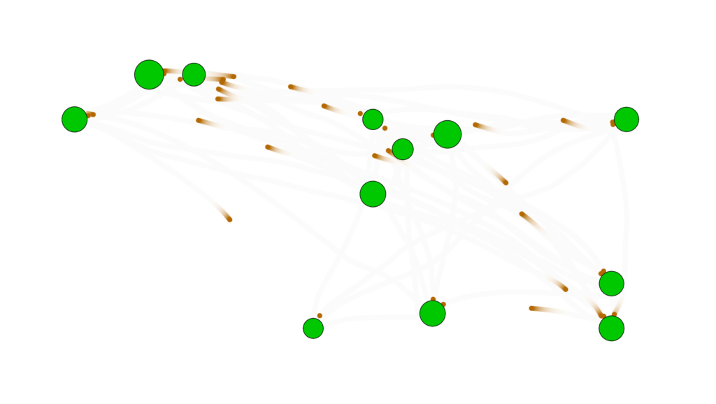
This is the current stage that I’m at. I added the vector field and changed the colors of the birds to brown without any stroke. The deviations in movement from the vector field were small at first but it was only after some time and by taking advantage of lowering the opacity of the background that I was able to notice the subtleties.
Future Improvements
Planned extensions to expand the system into multiple distinct modes:
1. No Mountains — Current baseline state
2. Mountains with Repulsion — Randomly placed mountains that birds navigate around using repulsion forces
3. Central Tree — A focal tree where birds travel back and forth in a more structured pattern
4. Nighttime / Daytime — Different visual states (e.g., color palette, lighting) to produce varied aesthetic outputs
These modes will increase the variety of visual outputs and support the requirement for multiple distinct operating states.
References
p5.js — p5js.org for the creative coding environment
Perlin Noise — Ken Perlin’s noise algorithm for smooth, natural-looking randomness
Flow Fields — Technique commonly used in generative art and particle systems
(although the noise() function in p5js is not exactly noise its still worth referencing)
This project expands on my assignment 3 project, where particles navigated a maze using goal attraction, wall repulsion, and turbulence. The midterm version adds multiple modes to explore different particle behaviors: refined maze navigation, free-flow turbulence, oscillating attractors, and dual attractors. The aim is to create diverse visual outputs and experiment with particle interactions, motion patterns, and color dynamics.
Implementation Details
The system now has a mode-based structure, allowing easy switching between behaviors using key presses (1–4). Each mode has its own settings for particle count, trail transparency, force strengths, and colors. Particles have variable sizes and colors, with trails rendered dynamically. Goals can be static, oscillating, or dual, depending on the mode.
Currently, walls are only implemented in Mode 1, the refined maze navigation mode. This is intentional for the progress version because Modes 2–4 are focused on exploring other behaviors, such as turbulence fields and moving attractors, without the influence of walls. Walls will be added to all modes in the final version to enhance particle interactions and visual complexity.
The reason for keeping the previous code is that the core particle and force mechanics are solid, so the current version builds on that foundation while adding more modes, dynamic goals, color variations, and adjustable parameters.
Key code highlights:
Mode system for switching between particle behaviors.
Particle class with forces: goal attraction, wall repulsion, and turbulence.
Dynamic goal movement in oscillating and dual-attractor modes.
Adjustable parameters for particle appearance, motion, and trail transparency.
Walls implemented in Mode 1, with plans to expand to all modes in the final version.
Progress
Base Code(Assignment 3):
Current state:
Mode changes with number: 1, 2, 3 and 4.
Reflection
The system is modular and flexible, making it easy to tweak parameters and add new behaviors. Next steps include creating more visually distinct modes, experimenting with more complex attractors or obstacles, and improving color and trail effects to produce final high-resolution outputs suitable for A3 prints.
ConceptFor my midterm project, I’m creating “Digital Kente,” a generative art system inspired by Ghana’s traditional Kente cloth. Kente originates from the Ashanti Kingdom and is deeply symbolic – each color represents something (gold for royalty, green for growth, red for passion) and the geometric patterns tell stories. Instead of creating organic, flowing generative art, I’m constraining the system to produce structured, geometric patterns that echo the woven textile tradition. The challenge is translating the craft of weaving into code while maintaining cultural authenticity.My system uses horizontal bands with different geometric motifs – zigzag diamonds, checkerboard patterns, diamond shapes, and horizontal stripes – all arranged like traditional Kente strips. Each band uses specific color combinations from authentic Kente palettes extracted from reference images. The patterns are grid-based and angular, mimicking how warp and weft threads create precise geometric designs through repetition and intersection.Cultural Context:
Kente isn’t just decorative – it carries meaning. The geometric patterns I’m implementing (zigzag diamonds, checkerboards) are traditional motifs with cultural significance. By bringing Kente into generative code, I’m exploring how traditional craft techniques can inform computational creativity while respecting the cultural heritage. Inspiration:
-Traditional Ghanaian Kente weaving patterns
-The geometric precision and bold color blocking of woven textiles
-How simple thread intersections create complex visual patterns
-Memo Akten’s approach to mathematical constraints creating variety
Some Kente Samples
Current Sketch
Milestones and Challenges
Milestones
-Researched traditional Kente patterns and extracted authentic color palettes
-Implemented grid-based system for geometric precision (20px cells)
-Created 4 distinct pattern types: zigzag diamonds, checkerboard, diamond motifs, and horizontal stripes
-Developed band system where each horizontal strip uses different patterns
-Added palette switching between Ashanti (warm) and Ewe (bold) color schemes
-Implemented texture lines to simulate woven thread appearance
Challenge 1: Maintaining Cultural Authenticity While Being Generative
My biggest struggle has been balancing algorithmic freedom with cultural respect. Early versions used smooth Perlin noise and organic curves – it looked generative but didn’t feel like Kente at all. Real Kente is precise, geometric, and structured. The breakthrough was realizing I needed to constrain the generative system rather than make it more random. By limiting patterns to grid-aligned shapes, sharp angles, and bold color blocks, the output finally started resembling actual woven cloth. The lesson: sometimes creative constraints (cultural traditions) produce better results than total freedom.
Challenge 2: Color Distribution Balance
Kente cloth doesn’t use colors randomly – certain colors dominate while others accent. My first attempts assigned random colors to each cell, which created visual noise rather than the bold color blocking you see in real Kente. I solved this by creating “band colors” – each horizontal band gets a curated subset of 2-3 colors from the full palette, not all 5. This mirrors how traditional weavers select specific thread colors for each strip. Now band 1 might use gold/orange/black, while band 2 uses green/red. This creates visual rhythm and hierarchy instead of chaos.
Current System Architecture
The system is organized into layers:
1. Color Palettes:
Extracted from actual Kente cloth samples
Two palettes: Warm Ashanti and Bold Ewe
Each band selects a 2-3 color subset for cohesion
2. Band System:
Canvas divided into horizontal bands (8 cells high)
Each band assigned one of 4 pattern types
Patterns cycle predictably: zigzag → checker → diamond → stripes → repeat
3. Pattern Functions:
drawZigzagBand() – Creates diagonal zigzag forming diamonds
drawCheckerBand() – 2×2 checkerboard with alternating colors
drawDiamondBand() – Concentric diamond shapes
drawStripeBand() – Horizontal color stripes with vertical texture
4. Animation:
Subtle time-based offsets in pattern calculations
Creates gentle “breathing” effect without losing structure
Can pause/resume with mouse click
Next Steps
Moving forward, I plan to:
-Implement multiple operational modes (particle weaving, harmonic oscillation, flow field variants)
-Add resolution scaling for A3 print size (2480 × 3508 px)
-Integrate traditional Ghanaian sounds (weaving sounds, drumming) for cultural immersion
Reflection So Far
The most valuable lesson from this project is understanding that constraint breeds creativity. By limiting myself to geometric shapes, grid alignment, and traditional color combinations, I’m forced to be more thoughtful about every design decision. This is similar to how real Kente weavers work within the constraints of their looms and thread colors yet produce infinite variety.
Working with cultural source material has changed my approach to generative art. Every design choice now asks: “Does this honor the tradition?” rather than “Does this look computationally interesting?” The planned audio integration will take this further – transforming the project from a purely visual experience into something that engages multiple senses with traditional weaving sounds and Ghanaian drumming.
The system already produces distinct looks depending on which patterns align, how colors distribute, and where the animation phase is captured. Once I add the additional modes and layer in traditional sounds, the generative space will expand while maintaining Kente’s visual and cultural language.
This project explores bacterial life inside a petri dish through the logic of binary fission. I was drawn to the simplicity of exponential growth. One cell becomes two. Two become four. Four become eight. That pattern is mathematically precise, yet visually it can feel organic and alive.
The petri dish acts as both a laboratory setting and a contained world. From the perspective of the bacteria, this circular boundary is their entire universe. Growth is not aggressive. It is natural, repetitive, and inevitable.
Through this project I am trying to visualize how simple systems can produce complex spatial transformation. The tension between geometric symmetry and organic movement is central to the concept.
System Design
The system is built around exponential growth using 2ⁿ logic.
It starts with one cell at the center. Each click doubles the generation. Each generation forms a new ring.
Everything is placed radially so the growth feels intentional and structured. At the same time, each cell has slight motion driven by noise so it does not feel like a static diagram.
I also introduced generational color shifts and soft background fades so the system leaves trails, almost like activity inside a petri dish.
The interaction is simple. Click and it divides. The simplicity is important to me. I did not want complicated controls. I wanted the act of division to feel immediate.
Prototype 1
The first prototype was very minimal.
It only tested the binary fission logic and radial placement. No sound. No complex motion. Just structure.
Visually it looked clean but almost too perfect. It felt more like a scientific chart than something alive. But it helped me understand how strong the doubling pattern actually is. Even in its simplest form, it already had presence.
That prototype gave me confidence that the system itself was strong enough to build on.
Current Version
The current version feels more alive.
Each cell now wiggles slightly within a constrained space. The trails create a sense of time passing. Multiple colonies can grow at once, which makes the space feel like an ecosystem rather than a single event.
The aesthetic has shifted away from realistic biology and more toward a luminous, speculative petri dish. It feels less clinical and more atmospheric.
I am excited about how something so rule based can still feel organic.
Concerns
I am still figuring out how to balance symmetry and irregularity.
Sometimes the radial placement feels too perfect. Real biological systems are not perfectly spaced. I may experiment with slight offsets to make the growth feel less mechanical.
Performance also becomes a concern at higher generations. The exponential logic is beautiful, but it scales quickly.
I also want the motion to feel softer and less jittery. I want it to feel intentional, not random.
Improvements for Final Midterm
For the final submission, I want to:
Refine the motion so it feels more like soft bodies. Experiment with subtle asymmetry. Introduce multiple modes, possibly a strict geometric mode and a more organic mode. Test higher resolution rendering for A3 printing.
I feel like the core idea is strong. Now it is about refinement and sensitivity.
AI Disclosure
I used AI briefly to help refine parts of the exponential logic and tune motion parameters while troubleshooting performance.
My main inspiration came from this video: Instagram
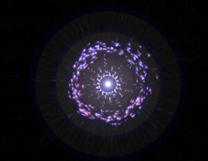
For this project, I chased the feeling of something between a pulsar and a deep-sea creature. The working title became Melancholic Bioluminescence, which sounds like a Spotify playlist but the fun thing about creating projects is having full authority and ownership over everything and its my sketch so I’ll name it that.
The core interaction is simple and satisfying to say out loud: hold your mouse down, energy accumulates, release it to detonate. Hold longer, bigger explosion. That’s the entire loop. What makes it interesting is the texture of the accumulation. Particles spiral inward like a black hole, and the glow resembles energy accumulating within that blackhole.
Before writing a single line, I sketched the architecture on paper. The system has three major layers of responsibility: the global state (are we holding? are we exploding? what’s the charge level?), the particle population (a pool of objects that each manage their own physics), and the vfx (trails, embers, glow pulses, which are short-lived visual elements that don’t need the full particle class). I accumulated my notes and compiled them into a beautiful psuedocode that I can follow, this is me abusing what I learned taking Data Structures and honestly desgining the system beforehand works for me really well
please check the pdf for the psuedcode because there’s this ANNOYING issue that no matter whats the scale of the screenshot I am uploading its always so blurry and small.
I also want to disclose that AI helped me with many mathematical sections within this sketch, I wouldn’t be able to understand the math or get around it on my own I think. But I promise my usage is not excessive or dependent and I actually use it to learn haha
Anyway, I started writing attributes for the particle class and oh boy they added up QUICKLY. Here’s a snippet. I tried assigning random values manually but it was very very hard to find the sweet spot for everything so I used some help from AI to assign the proper values to those attributes and I tweaked them a little bit and got really good results.
A useful frame for interactive generative art is the state machine. This sketch has three primary states that produce visually distinct experiences, and the transitions between them are where most of the design work happened.
Idle state: No mouse interaction. 80 particles drift across the canvas on Perlin noise. Each particle has its own noise offset, frequency, and speed. The result is slow, organic, slightly hypnotic. The palette sits in the 228-288 HSB hue range (blue through violet) and particles breathe gently at a rate of 2 cycles per second. This is the sketch’s resting face, and it needs to be beautiful enough to watch on its own.
Charging state: Mouse held. New particles spawn at the edge of the screen and get pulled toward the cursor which acts as an attractor. Spawn rate accelerates from 1/frame to 18/frame as charge approaches maximum. The vortex arms appear past 8% charge: three logarithmic spirals that rotate faster as charge builds, drawn with beginShape()/vertex() and per-vertex stroke colors that fade toward the outer edge. The glow orb grows around the cursor. Screen rumble starts at 60% charge. Particles near the cursor compress and brighten. The hue of nearby particles shifts toward 305, a hot magenta-violet. Every visual element does the same narrative work: energy is accumulating.
Explosion state: Mouse released. This is tiered across four discrete levels (0 through 3) based on charge thresholds at 0.25, 0.55, and 0.85. Tier 0 is a gentle push. Tier 3 is a white-flash, screen-shake, 800-pixel-radius detonation that spawns up to 70 child particles from split candidates nearest the blast origin. Each particle in blast range gets a force vector calculated from distance falloff (pow(1 - d/blastRadius, 2)), a random rotation drift, and a behavior assignment weighted by proximity to center and charge level. The explosion duration scales with charge, from 1.4 seconds to 4 seconds. The slowdown at high charge gives full-tier explosions a cinematic quality: the cloud expands, holds, then dissipates.
The variation space this produces is wide. A quick series of light taps creates a dotted constellation. Holding in one place while moving slightly creates smeared, comet-like trails. A patient full charge, held long enough to feel the rumble, produces a different kind of satisfaction.
the scariest things about this project were two things braided together: performance under additive blending with 700+ particles, and making the multi-behavior explosion feel coherent rather than random.
Additive blending (blendMode(ADD)) is visually spectacular. Overlapping particles bloom into white rather than muddy brown. The cost is real though: each ellipse composites against everything underneath it. With three ellipses per particle (the outer glow halo, the mid-glow body, and the bright core), plus trail objects, plus embers, a naive implementation at 700 particles hits framerate problems fast. The risk was a beautiful system running at 20fps. I ran many optimization processes but then I migrated to VS code which was MUCH smoother but I don’t know how smart that is going to be because in the end I’m gonna have to embed the sketch in p5.js web editor so it wouldn’t make sense or a difference that it runs smoothy on my device but its laggy on the website.
The mitigation strategy relies on hard caps with graceful degradation. Particles cap at 600 during charging and 700 overall. Trails cap at 1200 objects. Embers die slowly at life -= 0.003 per frame, about 333 frames of life. The three-ellipse draw call per particle uses deliberately low-resolution sizes: the outer halo is s*4, the body s*2, the core s*0.6, where s is typically 1.8-4 pixels. The glow effect comes from accumulationof tiny translucent shapes. The drawGlow() function uses 50 layered ellipses for the cursor glow, each with an alpha under 4, nearly invisible on their own.
For the behavior system, the risk was that five different particle behaviors during explosion would read as a mess of conflicting physics. To test this, I implemented behaviors one at a time and ran the explosion at full charge with only that behavior active, watching whether each produced a readable visual signature. BEHAVE_COMET needed the highest speed and the lowest drag (0.99 vs the standard 0.93-0.97) to produce visible streaks. BEHAVE_BOOMERANG needed the timer offset: if the return force kicked in immediately, particles just wobbled. They needed to actually leave the origin first. BEHAVE_FLUTTER was the most unpredictable and required the dampening multiplier (vx *= 0.985) to prevent runaway acceleration from the oscillating force.
The assignBehavior() method’s probability table weights behavior by charge level and proximity to blast center. Close-in particles at high charge get COMET and SPIRAL; far particles get RADIAL and FLUTTER. This creates a natural visual structure: a dense bright core of fast-moving comets surrounded by a slowly oscillating outer cloud. The explosion has a center and a periphery, which reads as physically plausible even though the physics are entirely invented.
The remaining uncertainty heading into the midterm is whether the vortex spiral arm rendering, which uses nested beginShape()/endShape() with per-vertex stroke calls, holds up on lower-end hardware. The core mechanic, the charge-and-release loop, and the explosion tier system all feel solid. The scary part is mostly tamed.
But there comes another problem. I don’t like the black background so I decided to create a galaxy background. I had a rough idea how to make it but I had to do some research.
Guess what, all of those links were useless. I found nothing of help but I didn’t want to give up. so I found this reddit post and I found this page and I follwed the principles and methods in the article to create something cool.
I tried to upload the gif of the animated image but I got this error so I will just upload a screenshot unfortunately.
I really dont know why the resolution is so low my monitor is 4k resolution and honestly it’s too late for me to worry about this. Anyway, I would love to go with the galaxy design but unfortunately it lags like HELL even on VS code, maybe I’ll book office hours and see how I can troubleshoot this.
my next steps for this is to figure out the background and also try to replicate the main inspiration video because right now everything feels flat and I am starting to hate it.
I’m building a generative desert landscape. Not a drawing of a desert, a system that grows one. Dunes form, shift, break apart, and settle, all on their own, driven by wind, tremors, and rain.
The title is “Shifting Grounds.”
The system moves through four phases like a timeline:
Wind → Ground Tremor → Rain → Stillness
Wind pushes sand around and builds dunes
Ground Tremor shakes things up, dunes collapse and spread out
Rain smooths the surface through erosion
Stillness everything settles. The terrain stops changing. This is the frame I export for my A3 prints
The simulation runs once and ends. It doesn’t loop.
Why a Desert?
I’m from the UAE. The desert isn’t just a landscape to me, it’s something I grew up around. I’ve always noticed how dunes shift and reshape themselves. Sand looks still but it never really is.
I want to explore that through code. How do dunes actually get their shape? Why are some tall and some flat? What happens when wind hits a ridge? This project is my way of digging into those questions and turning them into generative art.
Design — How Will It Work?
The Height Map
Instead of simulating thousands of sand particles (which is way too complex and slow), I’m using a height map. It’s just an array:
Each index is a column on the canvas. The value is how tall the sand is at that spot. When I draw it, I fill from the bottom up to the height. That gives me a terrain profile, like a side view of the desert.
Why this approach:
Way more stable than particles
Easier to control
Better for high-res A3 output
Clean and simple
Rendering
The look is minimal. Warm sandy monochrome palette. Shading is based on slope:
fill(baseColor - slope * contrast)
Steep slopes = darker. Flat areas = lighter. This fakes sunlight hitting the dunes from the side and creates a 3D look using just math. No textures, no images, just numbers and color.
Code Design — Functions, Classes, Structure
Here’s how I’m planning to organize the code:
windPhase() — moves sand using Perlin noise for wind direction and strength. After moving sand, it checks slope stability (angle of repose) so dunes don’t become unrealistically steep
tremorPhase() — lowers the stability threshold temporarily so dunes collapse and spread. Adds small random jitter to simulate vibration
rainPhase() — averages each column’s height with its neighbors. This is what erosion does, peaks go down, valleys fill up, everything smooths out
renderTerrain() — draws the height map with slope-based shading
State Management
A variable like currentPhase controls which phase is active. Each phase runs for a set number of frames, then transitions to the next:
WIND → TREMOR → RAIN → STILLNESS
In stillness, the draw loop still runs but nothing changes. The terrain is frozen in its final form.
Key Variables
heightMap[] — the core data. One value per pixel column
windStrength — controlled by Perlin noise, varies across space
maxSlope — the angle of repose. How steep sand pile can be before it slides
currentPhase — which phase the system is in
phaseTimer — counts frames in each phase
Interactivity (Planned)
Different noise seeds = different landscapes each run
Keyboard controls to adjust wind strength or skip phases
Parameter presets for different “climates” (strong wind, heavy rain, etc.)
States and Variations
Each run of the sketch will look different because of Perlin noise; different seeds create completely different dune formations from the same rules. That’s what makes it generative. I don’t place the dunes. The algorithm does.
For my three A3 prints, I plan to create variation by:
Changing the noise seed (different dune shapes)
Adjusting wind strength and direction (some runs make tall, sharp dunes, others make gentle rolling ones)
Varying how long each phase lasts (more wind = more dramatic terrain, more rain = smoother result)
The final stillness frame from each run becomes a unique print.
The Scariest Part
The most frightening part of this project is the wind simulation.
If sand transport is too strong, everything flattens instantly, and no dunes form. If the slope stability rules are too strict, the terrain freezes before anything interesting happens. The whole project depends on finding the right balance between these forces.
What I Did to Reduce This Risk
I wrote a basic prototype that tests the two core mechanics together: wind transport and slope stability.
This isn’t the final system. It only has the wind phase. But it confirms that the core mechanic, the hardest part, actually works. The tremor, rain, and stillness phases will be simpler to add on top of this foundation.
Other Risks I’m Watching
The final print might look too simple on A3 paper. Since it is just a 1D height map, it could feel flat. I need to test it early. If it looks too basic, I might add more depth, like a fake 3D effect or layered lines. I will decide after the full system is working.
References
R.A. Bagnold — The Physics of Blown Sand and Desert Dunes (1941).
Angle of Repose — From granular mechanics. The maximum steepness a pile of sand can have before it slides.
Ken Perlin — Perlin Noise (1983).
Soil Liquefaction — When vibration makes sand temporarily act like liquid.
Aeolian Transport — The geological process of wind moving sand.
For the midterm I decided to go back to space theme like I did in assignment 3. I really liked the design of the planets I came up with and wanted to possibly further explore that design with adding particles as an addition. I want again to use the planets as attractors but I would like to explore the idea of using the particle systems as little particles in space that go around these planets and make different constellations like Saturn’s ring.
Implementation
Background atmosphere
Stars placed in the background randomly.
A starfield with subtle twinkling for texture and scale.
Planet body
A solid planet drawn with shadows and rings to give depth.
Ring particle system
Each particle is assigned a target ring radius (three radius “bands”).
Motion is driven by a combination of forces:
Inward pull (gravity-like) to keep particles bound to the planet.
Tangential swirl to create orbit motion.
A spring force that pulls particles back toward their target radius so the ring stays structured.
Light damping/drag to keep it smooth and stable.
States/variation
At this point in time I still don’t have multiple states of the sketch, I am still thinking about what I could make different exactly for now some ideas were either placing different kinds of planets that have varying gravitational pull or removing the planets to create galaxy like objects. Or potentially giving an option to add multiple planets.
Scary parts
Right now the scariest part was actually making the particles go in a circle around the planet. I achieved this by doing the following:
First I calculate the vector pointing from a particle to the planet
let toCenter = p5.Vector.sub(planet.pos, p.pos);
let d = max(toCenter.mag(), 1);
toCenter.normalize();
After which I create a tangential force which actually gives the particles the circular motion
let tangential = createVector(-toCenter.y, toCenter.x);
tangential.mult(0.22 * planet.spin);
p.applyForce(tangential);
I also added some pull to keep the particles from going away
let grav = toCenter.copy().mult(0.14 * planet.massScale / (1 + d * 0.006));
And that’s how I created the ring around the planet. I am just a little worried if making the galaxy style sketch would bring more complexity to the design and if I will need to use something different for the particle movement.