Buernortey – Assignment 10

Concept

Erosion is a physics simulation of a rocky mesa breaking apart under falling debris. The idea came from thinking about how landscapes that look permanent are always being shaped by small, repeated impacts over time. I wanted to use Matter.js not just to show objects falling but to model a process. The terrain starts whole and breaks down based on how hard things hit it.

Code I Am Proud Of

The collision event handler is the center of the piece. It does not react to every contact. It reads the speed of the incoming rock and only shatters a terrain block when the impact crosses a threshold. This makes the simulation feel grounded. Slow rocks bounce off. Fast rocks break things.


Events.on(engine, 'collisionStart', function(event) {
  for (let pair of event.pairs) {
    let { bodyA, bodyB } = pair;
    let rock = null, ter = null;

    if (bodyA.label === 'rock' && bodyB.label === 'terrain') { rock = bodyA; ter = bodyB; }
    if (bodyB.label === 'rock' && bodyA.label === 'terrain') { rock = bodyB; ter = bodyA; }

    if (rock && ter) {
      let impactSpeed = Vector.magnitude(rock.velocity);
      if (impactSpeed > 3.5) {
        let idx = terrain.findIndex(t => t.body === ter && !t.broken);
        if (idx !== -1) shatterTerrain(idx, impactSpeed);
      }
    }
  }
});


I am also proud of the shatterTerrain function because it does three things at once when a block breaks. It triggers a screen shake scaled to the impact force, spawns a flash at the contact point, and sends out a burst of dust particles that drift upward and fade out. Each of those effects runs from the same impact speed value, so they all feel connected.


Embedded Sketch

Milestones and Challenges

The first milestone was drawing the terrain. I wrote a heightmap function that builds a mesa shape, peaks in the center, and slopes toward the edges, with small random offsets per column to roughen the silhouette. I added a sky gradient and a highlight strip on the top face of each block so the structure looked like real layered rock before any physics was involved.

The second milestone was loading that terrain into Matter.js as static bodies. Each block became a rectangle body placed at the correct position. Drawing them back from their body positions confirmed the physics world and the visual layer matched.

The third milestone was getting rocks to fall with physical variety. Rocks now vary in size, fall speed, bounciness, friction, and spin. Density scales with size so large boulders hit harder. Wind drifts slowly over time toward a random target every three seconds, and the visual rain streaks angle to match. This step exposed the first real challenge: collision filters. Without explicit category and mask values set on each body type, rocks passed straight through the terrain. Setting category: 0x0002 on terrain and mask: 0x0001 on terrain fixed which bodies could interact with which.

The fourth milestone was the full shattering system with visual feedback. When a collision event fires and the impact speed clears the threshold, the terrain block is removed, fragments spawn and tumble, dust particles burst outward, a flash appears at the contact point, and the canvas shakes. The main challenge here was performance. Without cleanup, thousands of fragment, dust, and rock bodies built up below the canvas over time and slowed the simulation. Adding a per-frame filter that removes any body or particle whose position exceeds the canvas height solved the problem completely.

Reflection

The piece works well as a slow process. Dropping one rock at a time and watching the terrain wear down has a satisfying quality. The storm mode makes the erosion visible in seconds and shows how the system handles high load. The wind system adds unpredictability without feeling random because it drifts gradually rather than jumping between values.

For future work I want to add water. Fragments that collect at the bottom could be slowly submerged as a rising water level fills the valleys left behind by the erosion. I also want to track how many blocks have been destroyed and show it as a live counter so the viewer has a sense of scale over the life of the simulation.

References

The Nature of Code, Chapter 6: Physics Libraries Matter.js documentation on collision events and body properties

Buernortey – Assignment 9

Concept

In the deep ocean, bioluminescence is not just decoration. Many creatures glow brighter when threatened. Firefly squid, siphonophores, certain jellyfish species all do this. The light is involuntary. It is a biological fear signal, and every creature nearby can read it.

That is the idea behind this sketch. It is a flocking system where light and movement share the same variable. Each boid’s proximity to a descending predator controls both how hard it steers away and how brightly it glows. Fear is brightness. The swarm illuminates itself at the exact moment it is most in danger.

The piece moves through three acts. First, creatures drift in near-total darkness, sparse, slow, barely visible. Then a shadow descends from above. Not fast, not aggressive, just a pressure. The boids closest to it sense it first and begin moving away, the fear-glow spreading outward through the swarm. Finally the predator arrives fully and the swarm explodes outward in a burst of light. Then silence. The survivors scatter into the dark, dimmer than before.

Embedded Sketch

Code I’m Proud Of

The piece’s central idea lives in about ten lines inside the Boid class. this.fear is a single float between 0 and 1 computed from distance to the predator. It does two jobs at once: it scales the steering force pushing the boid away, and it is read by draw() to amplify the glow radius and opacity.

// Inside applyPhaseForces(), descend phase:
let toPred   = p5.Vector.sub(this.pos, createVector(pred.x, pred.y));
let d        = toPred.mag();
let fearZone = 280;

if (d < fearZone) {
  this.fear = map(d, 0, fearZone, 1.0, 0);
  toPred.normalize().mult(this.fear * 0.38);
  this.acc.add(toPred);
} else {
  this.fear = 0;
}

// Inside draw():
const baseAlpha = 0.60 + fearGlow * 0.40;
const glowR     = this.size * 2.2 + fearGlow * 5;

The same number that moves the creature also lights it up. I did not need a separate brightness system. That reduction felt like the sketch finding its own logic rather than me imposing one.

Milestones and Challenges

Milestone 1: Basic flocking

The first working version was just the three steering forces running on a plain black background. No phases, no predator, no glow. Getting alignment, cohesion, and separation balanced took more time than expected. At equal weights the boids collapsed into a tight unmoving ball. I had to bring cohesion down significantly and give separation more authority before the swarm started feeling alive.

Milestone 2: Adding bioluminescent glow

Once the flocking was stable I replaced the flat ellipse with a radial gradient halo drawn through drawingContext. This is where the creatures started feeling like they lived underwater rather than on a screen. I also added the teardrop body shape and started assigning each boid a random hue in the cyan-to-violet range.

Milestone 3: The predator as pressure, not shape

My first predator was a solid dark ellipse and it looked like a game obstacle. The fix was removing any hard edge entirely and replacing it with a radial gradient that fades to nothing — an absence of light rather than a presence of shape. This one change made the whole sketch feel more like an environment and less like a simulation.

Milestone 4: Fear driving both movement and light

This was the central technical challenge. Once the predator was descending I needed the boids to respond to it — not just steer away, but glow brighter as they got closer. The insight was that these could be the same number. I computed this.fear as a map() of distance and fed it into both the physics and the renderer simultaneously.

Reflection

The fear-as-light mechanism worked the way I hoped. Watching the swarm light up at the moment of greatest danger, because of the danger, gave the piece a logic that felt biological rather than programmed.

A few directions I would take this further. Sound is the most obvious missing layer. The panic phase has a visual density that feels like it needs a corresponding audio response, something close to how Kurokawa synchronizes brightness and sound intensity. The predator could also be made reactive rather than scripted, hunting the brightest cluster in the swarm. This would create a feedback loop where fear-glow attracts the very thing the swarm is afraid of. Individual boid memory would also add depth. Creatures that were nearly caught could stay darker and more erratic for longer, while those that escaped early return to calm faster. Trauma as a behavioral variable rather than just a visual one.

References

Ryoichi Kurokawa’s audiovisual works were a direct influence, specifically how he treats light density as a rhythmic and emotional variable rather than aesthetic decoration. Robert Hodgin’s fluid creature systems shaped how I wanted the boids to feel: biological rather than mechanical. 

Buernortey – Assignment 8: The Shoal

Concept

Growing up in a fishing community in Ghana, I watched fishermen read the water. Not just the tides, but the fish themselves. A school of fish moves like a single organism, splitting around rocks, scattering from shadows, reforming behind the boat. No one fish is giving orders. The pattern emerges from each individual following a few simple rules about its neighbors.

That memory became the concept for this sketch. The Shoal is a system of 60 fish navigating an ocean current, staying together as a group, and reacting to a predator that tracks your mouse cursor. The behaviors are inspired directly by Craig Reynolds’ steering model: each fish knows nothing about the whole. It only senses what is close to it. Yet the group produces complex, lifelike motion.

The color palette is drawn from the Ghanaian flag (red, gold, and green), and each color encodes a live behavioral state. Green means a fish is flocking normally. Red means it is fleeing the predator. Gold means it has drifted away from the group and is wandering on its own.

A Highlight of Code I’m Proud Of

The piece of code I kept returning to is the flock() method, the behavior composer that decides frame by frame what each fish should be doing. What I love about it is how it uses the same underlying steering primitives in completely different combinations depending on context.

flock(others, pred, flow) {
  let d = dist(this.pos.x, this.pos.y, pred.pos.x, pred.pos.y);
  let fleeing = d < FLEE_RADIUS;

  if (fleeing) {
    // Run directly away from the predator at boosted speed
    let flee = this._flee(pred.pos);
    flee.mult(2.5);
    this.applyForce(flee);
    this.maxSpeed = FISH_MAX_SPEED * 1.5;
    this.bodyColor = PAL.red;
  } else {
    // Normal flocking: separation keeps spacing, alignment matches heading,
    // cohesion pulls toward the group center using arrive()
    let sep = this._separation(others);
    let ali = this._alignment(others);
    let coh = this._cohesion(others);

    sep.mult(1.8);
    ali.mult(1.0);
    coh.mult(1.2);

    this.applyForce(sep);
    this.applyForce(ali);
    this.applyForce(coh);

    // Flow field gives the fish a subtle current to drift with
    let flowForce = flow.lookup(this.pos);
    flowForce.setMag(this.maxSpeed * 0.6);
    let flowSteer = p5.Vector.sub(flowForce, this.vel);
    flowSteer.limit(this.maxForce * 0.5);
    this.applyForce(flowSteer);

    // Isolated fish switch to wander
    let neighbors = this._countNeighbors(others, COH_RADIUS);
    if (neighbors < 3) {
      this.bodyColor = PAL.gold;
      this.applyForce(this._wander());
    } else {
      this.bodyColor = PAL.green;
    }
  }
}


What made this click for me is that _arrive() is called inside _cohesion(), so even the group behavior uses the same arrive logic I first learned as a single vehicle seeking a target. One method, three behavioral contexts: cohesion toward the group center, the predator arriving at the cursor, and the wander behavior projecting a circle ahead of itself. Reusing the same primitive in different combinations was the most satisfying part of this assignment.

Embedded Sketch


Move your cursor to control the predator. Watch the shoal react. Fish nearest the predator turn red and scatter, isolated fish turn gold and wander, and the rest stay green and hold formation together.

Milestones and Process

Phase 1 — One fish, seek and arrive

I started with a single fish vehicle following the mouse. The goal was to make sure the arrive behavior felt right before scaling up, because arrive is the foundation everything else builds on. At this stage it was just one ellipse with a triangle tail, but the deceleration as it approached the cursor already felt organic.

The main challenge here was getting the arrive slowing to feel natural rather than mechanical. My first attempt applied the speed reduction too early, so the fish would crawl painfully slowly from far away before even reaching the target zone. I had to narrow the slowdown window to only the final 100 pixels, leaving full speed everywhere outside that range, before the motion started to feel right.

Phase 2 — Scaling to a shoal, adding flocking

I scaled from one fish to 40 using a loop and implemented separation, alignment, and cohesion as three separate steering forces composed together.

Tuning the force multipliers was the hardest part of this phase and took the most iteration. My first set of values had separation too weak, so fish constantly clipped through each other and the group looked like a blob rather than a school. Raising it too far in the other direction made the shoal explode outward and never reform. I also had alignment weighted too heavily early on, which made every fish lock into the same heading so rigidly that the group moved like a marching band rather than a living thing. Getting to sep × 1.8, ali × 1.0, coh × 1.2 took many small adjustments and a lot of watching the sketch run.

Phase 3 — Predator, flee, wander, and color states

The predator changed the whole feel of the sketch. Once a dark fish that tracked the mouse was introduced, the shoal became reactive rather than passive. Flee was implemented as a reversed seek: instead of steering toward the target, the fish steers directly away from it with a force multiplied at 2.5× for urgency.

The flee force caused a problem I did not anticipate. With the multiplier too high, fish near the predator would accelerate so violently that they shot across the entire canvas in a single frame and wrapped around to the other side, which looked completely wrong. I had to pair the force multiplier with a capped maxSpeed boost rather than an uncapped acceleration, so the urgency comes through in the speed increase without the motion becoming physically implausible. Getting the flee radius right also took several attempts. Too large and fish were permanently panicking even when the predator was nowhere near them. Too small and the reaction looked delayed and unconvincing.

Phase 4 — Flow field, ocean background, full fish anatomy

The final layer was a Perlin noise flow field that gives the whole canvas a gentle ocean current. Each fish looks up the flow vector at its position and applies it as a weak additional force.

The challenge here was finding the right weight for the flow force relative to the flocking forces. In early versions I had it too strong, and it completely overrode the cohesion and alignment behavior. Fish stopped schooling and just drifted in the same direction like debris, which defeated the whole point. Pulling it back to maxSpeed × 0.6 with a force limit at half of maxForce made it feel like an environmental influence rather than a controlling force — the fish push through it, but you can see them drifting slightly when nothing else is competing for their attention.

Reflection and Ideas for Future Work

The biggest surprise was how little code produces this result. The entire behavioral system, 60 fish with four distinct modes, comes down to three vector additions per frame per fish, each about five lines long. What Reynolds figured out in the 1980s still feels almost unreasonably powerful.

The Ghanaian flag palette was a natural choice for me. I had already used it in my midterm project, and it works well here because each color carries cultural weight while also reading clearly as a data signal. You understand the system’s state at a glance just from the color distribution across the canvas.

Ideas for future work include adding a real food source, a glowing anchor point the shoal seeks when the predator is far away, which would complete the full foraging cycle. Two competing shoals in different colors racing for the same food would also be compelling. Letting individual fish leave a faint pheromone trail that gradually fades would make the paths the school carves through the water visible over time. And sound would add another dimension: low ambient ocean audio that pitches up slightly when the shoal is stressed and fleeing.

References and inspiration:

  • The Nature of Code, Chapter 5 (Autonomous Agents) by Daniel Shiffman, which provided the steering force formula the entire system is built on
  • Craig Reynolds, Steering Behaviors for Autonomous Characters, the original separation, alignment, and cohesion framework
  • Braitenberg Vehicles, and the idea that complex behavior can emerge from extremely simple rules
  • Personal memory of fishing communities in the Central Region of Ghana

MIdterm Project – Adinkra Particle System

Midterm Project Overview

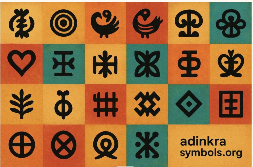
This project is a generative art system built in p5.js, centered on three Adinkra symbols from Ghana. Adinkra are visual symbols created by the Akan people. Each one encodes a philosophical proverb, a value, or a worldview that has been passed down through cloth, pottery, and architecture for centuries. Growing up Ghanaian, these symbols have always been part of my visual landscape. For this project, I wanted to bring them into a computational one.

The core idea is this: the symbols are invisible. There are no outlines drawn on screen. Instead, each symbol exists as a mathematical force field — a set of curves that attract particles toward them. Particles are born on the symbol’s edges, drift away through Perlin noise turbulence, and are pulled back by physics-based forces. What you see is not a drawing of the symbol. It is the symbol’s behavior, made visible through collective motion.

The system has four modes, switchable by pressing 1, 2, 3, or 4. Each mode corresponds to a different symbol or combination of symbols, with a distinct color palette drawn from the Ghanaian national flag: red, gold, and green on a black field.

Initially, the system had four modes built on particle-maze navigation — goal attraction, wall repulsion, and turbulence fields. The final version takes a completely different direction: instead of walls shaping particle paths from the outside, the symbol’s own geometry becomes the invisible attractor. The maze is gone. The symbol is the maze.

The Three Symbols

Choosing which Adinkra symbols to use was not a technical decision — it was a personal one. I needed symbols I could relate to and explain with honesty, not just describe. These three are the ones I keep returning to.

Mode 1 — Sankofa

“Se wo were fi na wosankofa a yenkyi” — It is not wrong to go back and retrieve what you forgot.

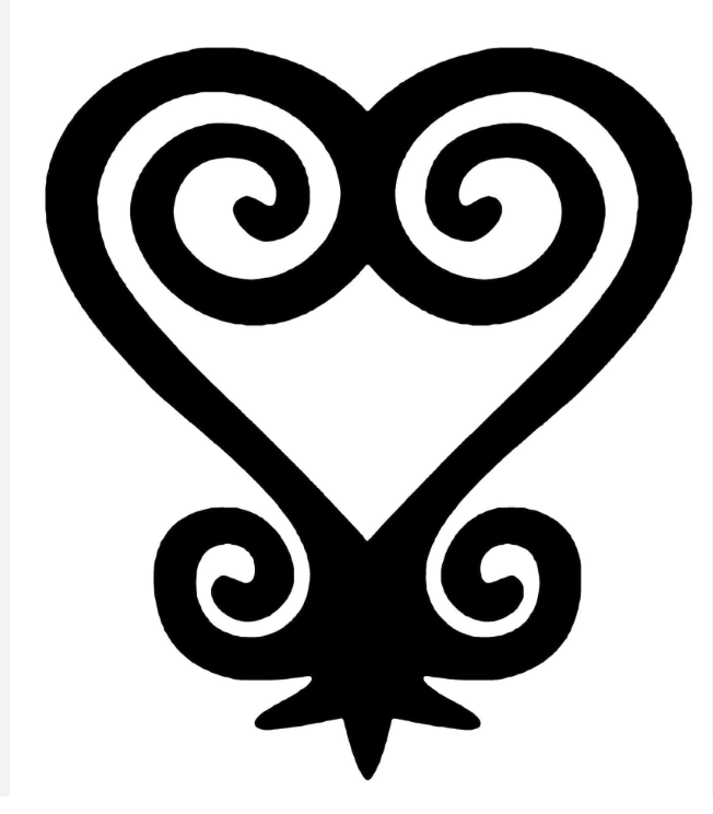
Sankofa exists in two visual forms. The one used in this project is the abstract heart form — the version stamped on cloth, carved into gold weights, and worn on ceremonial fabric across Ghana. The symbol is a heart body — two lobes that sweep down and meet at a pointed base — but what distinguishes it from a plain heart are the spirals. At the very top, where the two lobe lines meet in a V, each side continues past that meeting point and curls inward into the heart’s own interior. The left line curls down-right in a clockwise spiral, the right line curls down-left counter-clockwise. These inner spirals nestle inside the heart. At the bottom of the heart, flanking the pointed tip, two smaller spirals curl outward — away from the body, like feet planted on the ground. The whole symbol is bilaterally symmetric and deliberate in every curve.

As a Ghanaian studying abroad, this symbol means something specific to me. The further I move from home — geographically, culturally, academically — the more I feel the pull of that backward glance. Sankofa is not about being stuck in the past. It is about knowing what to carry with you.

In the system, Sankofa is rendered in red and gold — blood and heritage. Particles spawn across the full outline: both heart lobes, the two inner V-extension spirals, and the two outward bottom spirals. Perlin noise pushes particles away from the outline. A physics force pulls every particle back toward its travelling target point on the symbol. That constant tension between leaving and returning enacts the proverb directly in the particle physics.

Mode 2 — Gye Nyame

“Gye Nyame” — Except God. A declaration of the supremacy and omnipotence of God.

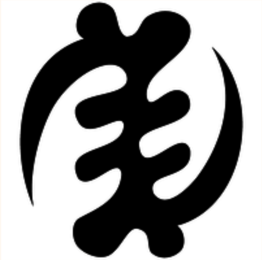
Gye Nyame is the most widely used Adinkra symbol in Ghana. You see it on walls, on fabric, on the backs of tro-tros, carved into doorframes, and on the Ghanaian 200 cedi(currency) note. It is not affiliated with any single religion — it expresses a universal acknowledgment that there is a force greater than human understanding. In Akan culture, Nyame is the origin and sustainer of all things.

The structure of Gye Nyame is unlike any other symbol. Running down the center is a chain of four alternating C-scroll knobs — bulging left, then right slightly lower, then left again, then right again — like the knuckles of a clenched fist stacked vertically. These give the symbol its distinctive textured spine. From the top of this spine, one large arm sweeps out to the upper-left in a wide arc, and its tip hooks back downward. From the bottom of the spine, a matching arm sweeps out to the lower-right and its tip hooks back upward. These two diagonal arms are not mirror images of each other across a horizontal axis — they are a 180-degree rotation of each other, which is why the symbol is described as chiral: it looks different from its own reflection. That diagonal asymmetry is the most identifiable thing about Gye Nyame.

In the system, particles spawn across all features — the four alternating spine knobs and both fishhook arms. Each particle travels along the outline continuously, with a sinusoidal oscillation displacing its target perpendicularly so the arms appear to breathe. The palette is gold and green — divine and natural, sun and land.

Mode 3 — Adinkrahene

“Chief of Adinkra” — greatness, charisma, and leadership.

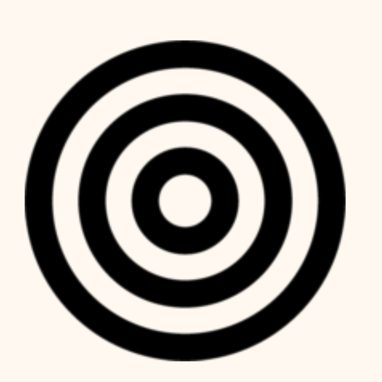
Adinkrahene — the chief of all Adinkra symbols — is structurally the simplest: three concentric circles. Its power is architectural. It is said to have inspired the design of many other Adinkra symbols, which is why it sits at the head of the entire system. Simplicity as authority.

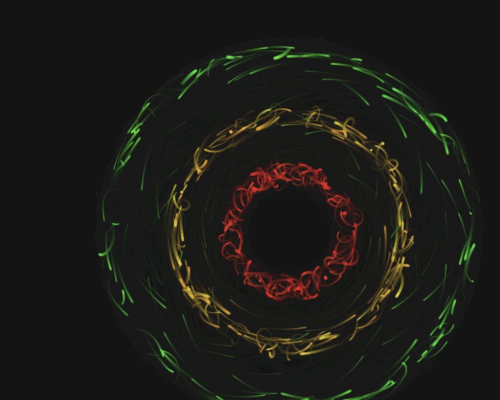
In the system, each of the three rings carries a different flag color: the inner ring is red, the middle ring is gold, and the outer ring is green. This mirrors the horizontal bands of the Ghanaian flag radiating outward from a center, the same way leadership radiates outward from a source. About 18% of particles are radiators — born at the center and travelling outward through all three rings before fading. They represent authority emanating from a single point.

Mode 4 — Composite

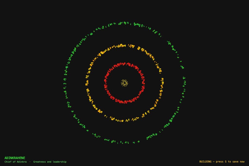
The fourth mode draws all three symbols at the same time using separate particle sub-systems. I wanted to experiment around it and see the outcome. The three force fields overlap and interact. Where Sankofa’s heart body overlaps with Adinkrahene’s inner ring, red particles from both systems cluster into unplanned concentrations. The symbols coexist the way traditions coexist, distinct but not isolated.

Implementation Details

The system is a single p5.js sketch organized into four layers: a mode system that handles keyboard input and configuration, a geometry layer that defines the mathematical outlines of each symbol, a physics layer that computes forces, and three particle classes — one per symbol — each managing its own movement, behavior, and rendering.

From the Progress Version to the Final Version

The progress version was a functional system built on maze navigation — particles moved through walls using goal attraction, wall repulsion, and Perlin noise turbulence. The technical foundation was solid. What it lacked was a conceptual anchor: the modes were mechanically distinct but did not say anything together.

The pivot to Adinkra symbols changed the project completely. Instead of walls shaping particle paths from the outside, the symbol’s own geometry became the invisible attractor. The maze walls were removed. The physics stayed. The symbols became the maze.

 Particle System

All four modes are built on a particle system. Each mode maintains a pool of 900 to 1,100 particles (2,400 in composite mode). Rather than destroying and recreating particles, the system calls reset() on a particle when it dies, recycling it with a new spawn position, velocity, color, and lifespan. This keeps memory usage flat and the frame rate stable throughout the session.

Every particle stores its previous position alongside its current one. Each frame, it draws a line segment from prev to pos before updating prev. This is what creates the motion trail. The trail length is controlled by fadeAlpha — the transparency of the dark wash applied over the entire canvas each frame. A lower value means longer, slower-fading trails.

// In draw() — dark wash creates motion trails
noStroke();
fill(0, 0, 7, fadeAlpha);
rect(0, 0, width, height);
// Inside any particle's show() method
show() {
  let a = (this.life / this.maxLife) * this.alp;
  stroke(this.hue, this.sat, this.bri, a);
  strokeWeight(max(this.r * (this.life / this.maxLife), 0.4));
  line(this.prev.x, this.prev.y, this.pos.x, this.pos.y);
  this.prev = this.pos.copy();
}

Forces and Newton’s Second Law

Particle motion is governed by F = ma. Each particle has a mass property. When a force is applied, it is divided by the particle’s mass before being added to acceleration. Heavier particles respond more slowly to the same force, which gives the system organic weight variation across the particle pool.

applyForce(f) {
  // F = ma  →  a = F / m
  this.acc.add(p5.Vector.div(f, this.mass));
}

In all three symbol modes, two forces act on every particle simultaneously. The first is a force toward a travelling target point on the symbol’s outline — this keeps the particle anchored to the geometry. The second is Perlin noise drift — this gives the particle organic, independent energy so it does not look mechanical. The balance between these two forces is what determines how tightly the symbol reads versus how alive the system feels.

update(sm) {
  // Advance t along the outline
  this.travelT += this.travelSpd * sm;
  if (this.travelT > 1) this.travelT -= 1;
  if (this.travelT < 0) this.travelT += 1;

  // Force 1: pull toward travelling target on outline
  let idx = floor(this.travelT * sankofaLUT.length) % sankofaLUT.length;
  let tgt = sankofaLUT[idx].copy();
  let toTarget = p5.Vector.sub(tgt, this.pos);
  let d = toTarget.mag();
  toTarget.normalize();
  toTarget.mult(constrain(d * 0.043, 0, 2.2));
  this.applyForce(toTarget);

  // Force 2: Perlin noise drift
  let na = noise(this.pos.x * 0.006, this.pos.y * 0.006,
                 frameCount * 0.003 + this.noiseOff) * TWO_PI * 2;
  let dr = p5.Vector.fromAngle(na);
  dr.setMag(0.11 * sm);
  this.applyForce(dr);

  this.vel.add(this.acc);
  this.vel.limit(3.2 * sm);
  this.pos.add(this.vel);
  this.acc.mult(0);
  this.life--;
}

Travelling Along the Outline (Orbital Motion)

The most important motion decision in the final version was the introduction of travelT — a normalized parameter (0 to 1) that advances along the precomputed outline look-up table every frame, at a random speed and random direction (some particles travel clockwise, some counter-clockwise). This is directly equivalent to how Adinkrahene’s ring particles advance their theta angle around the circle every frame.

Before this change, Sankofa and Gye Nyame particles only moved by being attracted toward a static nearest point on the outline. They jittered in place rather than flowing. Adding travelT gave them continuous directional motion along the symbol — the same quality that made Adinkrahene feel fluid.

// travelT advances along the LUT each frame — equivalent to
// theta advancing around Adinkrahene's ring.
// Random speed + random direction gives each particle
// independent orbital motion along the symbol outline.
this.travelT += this.travelSpd * sm;
if (this.travelT > 1) this.travelT -= 1;
if (this.travelT < 0) this.travelT += 1;

let idx = floor(this.travelT * sankofaLUT.length) % sankofaLUT.length;
let tgt = sankofaLUT[idx].copy();

Oscillation

Each particle has its own independent oscillation parameters: oscAmp (amplitude), oscFreq (frequency), and oscPhase (starting phase offset). Every frame, the particle’s target point is displaced sinusoidally perpendicular to the outline — so the symbol appears to breathe in and out rather than holding a rigid fixed shape. Because every particle has a different phase, the breathing is organic and asynchronous across the full outline.

// Compute perpendicular direction to the outline at target point
let toTgt = p5.Vector.sub(tgt, this.pos);
let perp  = createVector(-toTgt.y, toTgt.x);
if (perp.mag() > 0.01) perp.normalize();

// Displace target sinusoidally — symbol breathes in and out
let osc = this.oscAmp * sin(frameCount * this.oscFreq * sm + this.oscPhase);
tgt.add(p5.Vector.mult(perp, osc));

Perlin Noise

Perlin noise is used across all four modes to add organic drift to particle motion. Unlike random(), which produces sharp, uncorrelated values, noise() produces smooth continuous fields that evolve over time. The noise is sampled in three dimensions: x and y from the particle’s position, and a time dimension from frameCount multiplied by a small constant. The third dimension makes the field evolve slowly so the drift changes character over time rather than holding a fixed direction.

Each particle has a unique noiseOff value assigned at spawn. This offsets its position in the noise field so no two particles ever follow the same trajectory, even if they start from the same point. Without this, all particles drift in the same direction at the same time, which looks mechanical rather than alive.

// 3D noise: x/y position + time + unique per-particle offset.
// noiseOff ensures no two particles share the same noise trajectory.
let na = noise(
  this.pos.x * 0.006,
  this.pos.y * 0.006,
  frameCount * 0.003 + this.noiseOff
) * TWO_PI * 2;

let dr = p5.Vector.fromAngle(na);
dr.setMag(0.11 * sm);
this.applyForce(dr);

Warmup and Speed Ramp

A warmup system was added to solve a practical problem: the particles move quickly at full speed, making it difficult to capture clean screenshots for the three required export images. When a mode starts (or resets), modeFrame is set to zero. Each draw call, speedMult is computed by mapping modeFrame from the range 0 to 600 (about ten seconds at 60fps) to the range 0.18 to 1.0. This multiplier is applied to every dynamic value in all three particle classes — travel speed, noise magnitude, oscillation frequency, and the velocity cap. The system starts at 18% of full energy and smoothly accelerates to full speed over ten seconds.

During warmup, the HUD shows a pulsing “BUILDING — press S to save now” message so the optimal screenshot window is always clearly signposted. Pressing R resets the warmup ramp at any time.

// In draw() — ramps from WARMUP_MIN (0.18) to 1.0
// over WARMUP_FRAMES (600) frames, then holds at full speed
modeFrame++;
let speedMult = map(modeFrame, 0, WARMUP_FRAMES, WARMUP_MIN, 1.0);
speedMult = constrain(speedMult, WARMUP_MIN, 1.0);
// Inside every particle's update(sm) — sm scales all motion
this.vel.limit(3.2 * sm);

Geometry: Precomputed Look-Up Tables

Each symbol’s outline is defined as a series of cubic Bézier curves, sampled once at startup into a flat array of p5.Vector points called a look-up table (LUT). Sankofa has five segments (two heart lobes, two inner V-spirals, two bottom outward spirals) sampled into 800 points. Gye Nyame has seven segments (four knob scrolls, two arm segments each built from three chained cubics) also sampled into 800 points.

Rather than recomputing Bézier geometry inside the draw loop every frame, particles simply index into these arrays. This is what makes the system performant enough to run 1,100 particles per mode at 60fps. The LUTs are rebuilt whenever the canvas size changes (on R or mode switch) so the geometry always scales correctly to the canvas dimensions.

// Evaluate a cubic Bézier at t, push result into arr (canvas coords)
function sampleCubic(arr, ax, ay, bx, by, cx_, cy_, dx, dy, n) {
  for (let i = 0; i <= n; i++) {
    let t  = i / n;
    let m  = 1 - t;
    let x  = m*m*m*ax + 3*m*m*t*bx + 3*m*t*t*cx_ + t*t*t*dx;
    let y  = m*m*m*ay + 3*m*m*t*by + 3*m*t*t*cy_ + t*t*t*dy;
    arr.push(createVector(cx() + x, cy() + y));
  }
}
// Example: building the Sankofa LUT at startup
// Each call samples one Bézier segment into sankofaLUT.
// All five segments (heart lobes, inner spirals, bottom spirals)
// are sampled once and never recomputed during the draw loop.
function buildSankofaLUT() {
  sankofaLUT = [];
  let k = K();             // scale factor = min(w,h) * 0.0031
  let nH = floor(LUT_SIZE * 0.30);  // points per lobe segment
  let nS = floor(LUT_SIZE * 0.08);  // points per spiral arc

  // Left heart lobe: bottom point → V at top center
  sampleCubic(sankofaLUT,
    0, 95*k,  -40*k, 70*k,  -82*k, 28*k,  -82*k, -20*k,  nH);

  // Left inner spiral: from V, curls down-right
  sampleCubic(sankofaLUT,
    0, -28*k,  12*k, -42*k,  36*k, -40*k,  38*k, -22*k,  nS);

  // ... (right lobe, right spiral, bottom spirals follow same pattern)
}

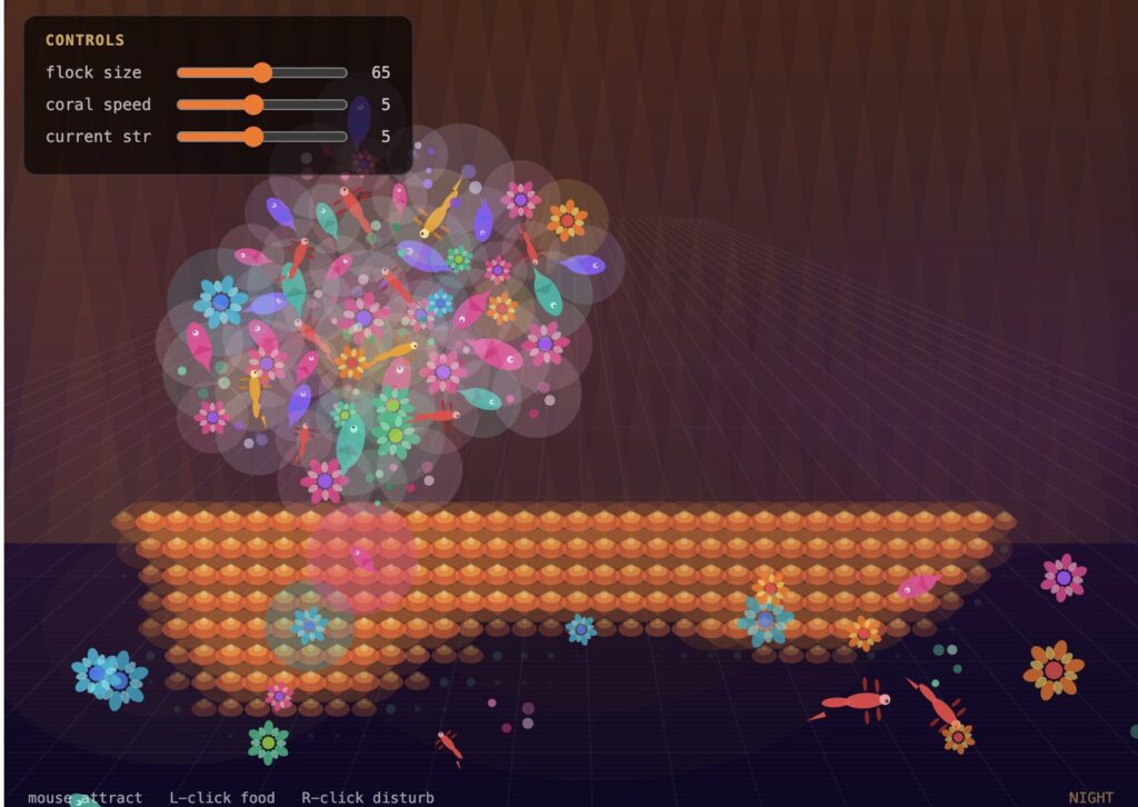
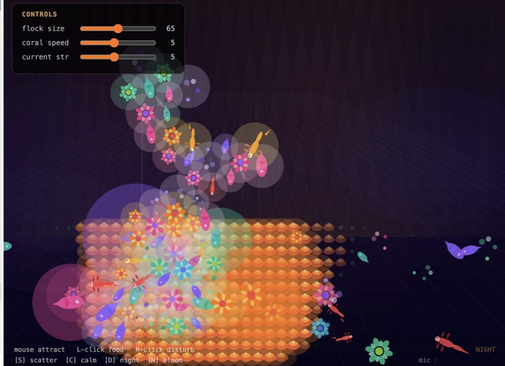
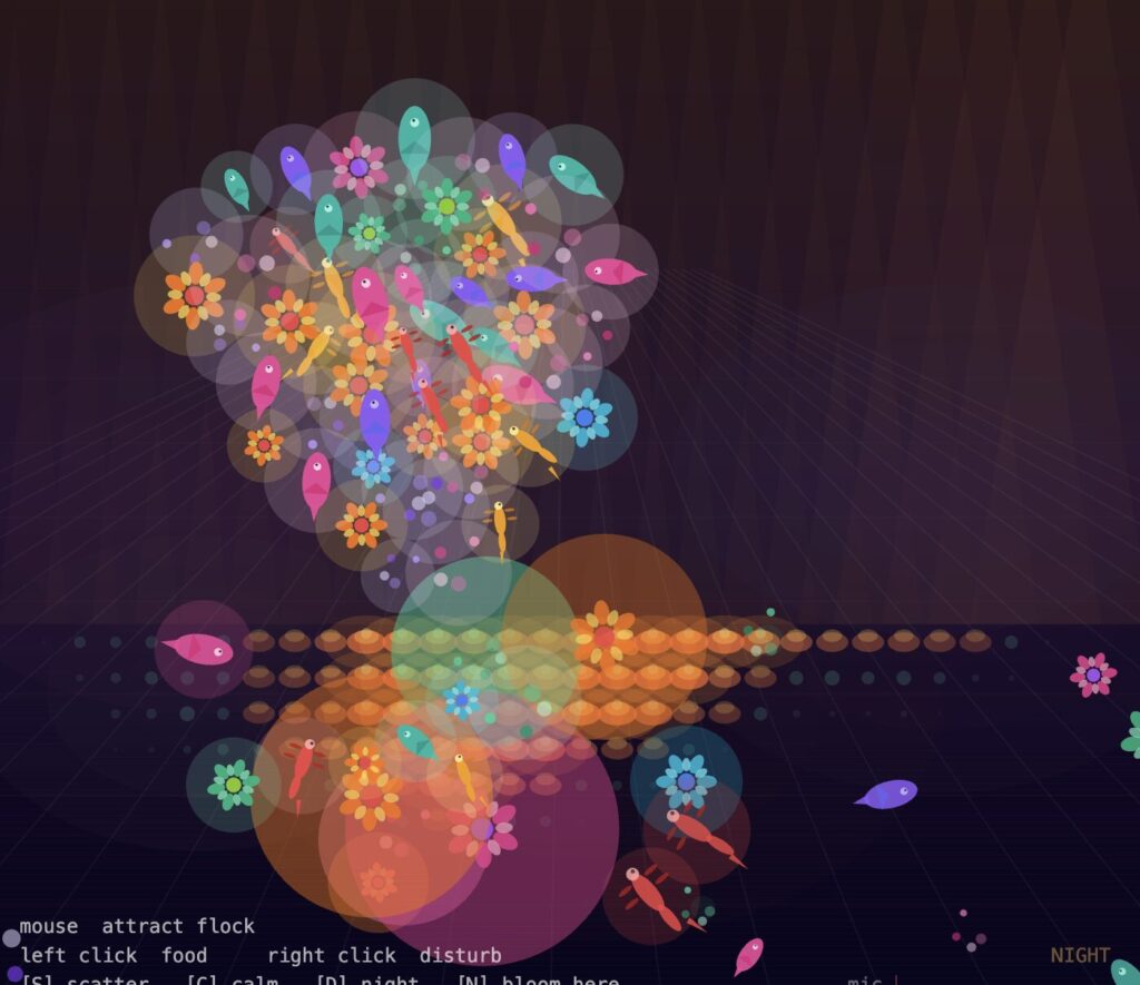
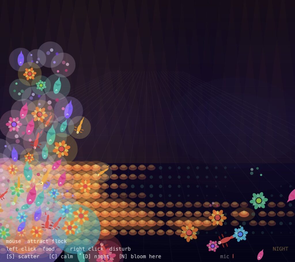
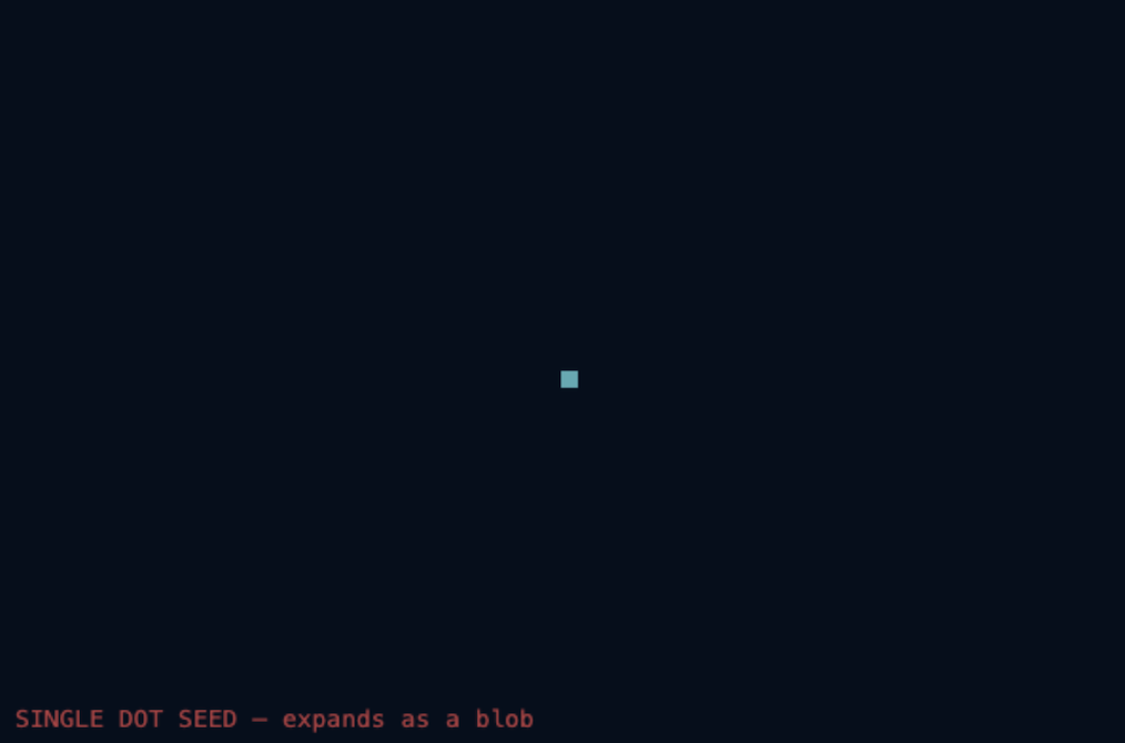
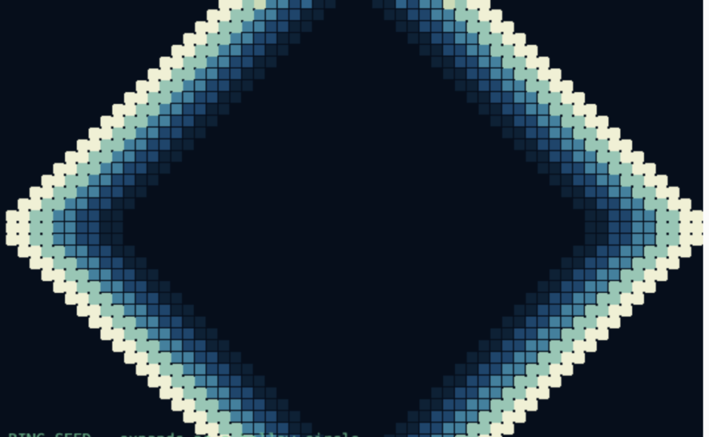
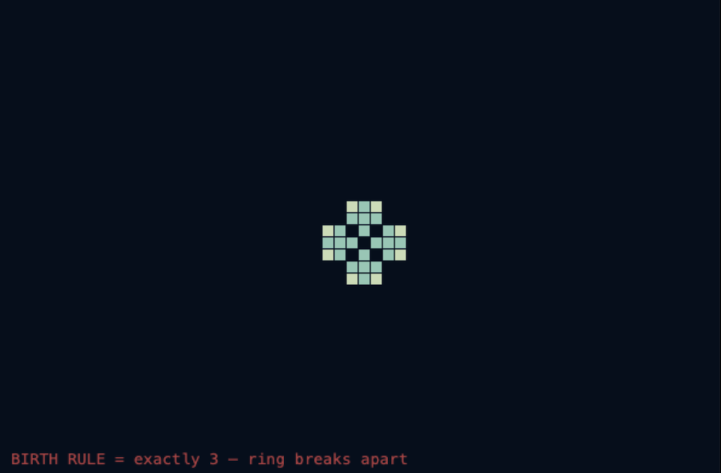
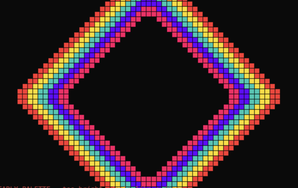
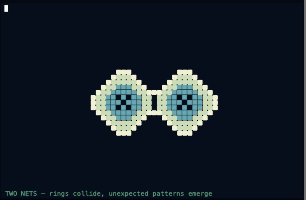
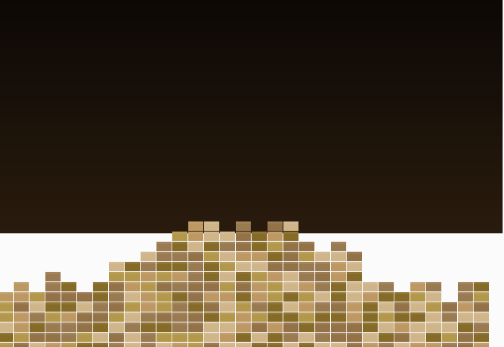
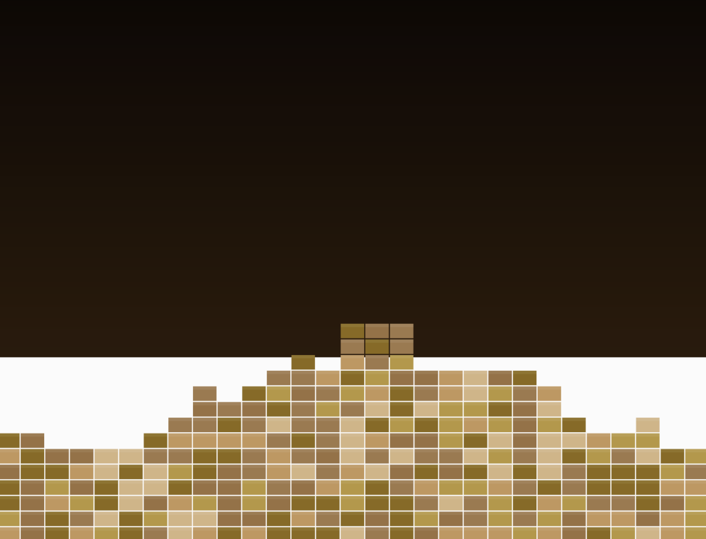
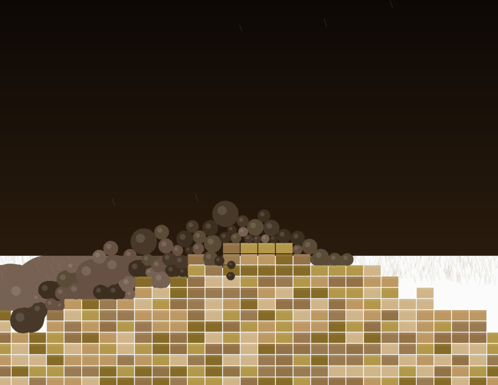
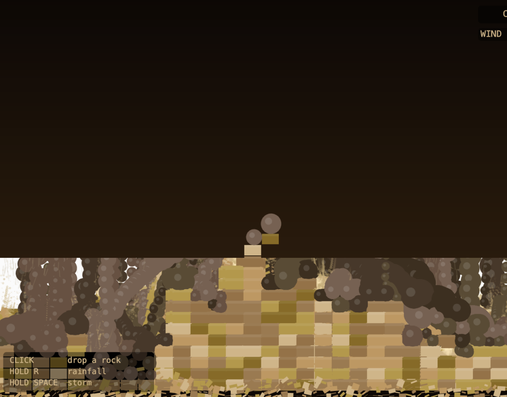
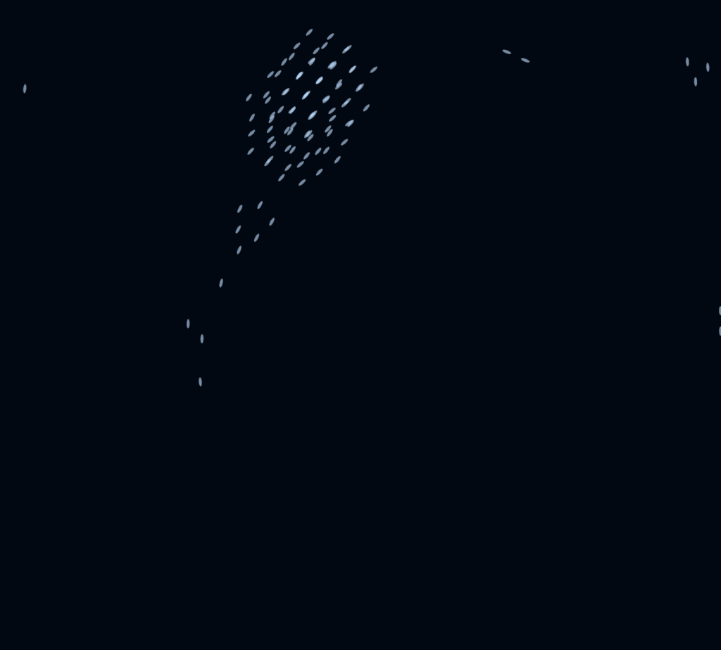
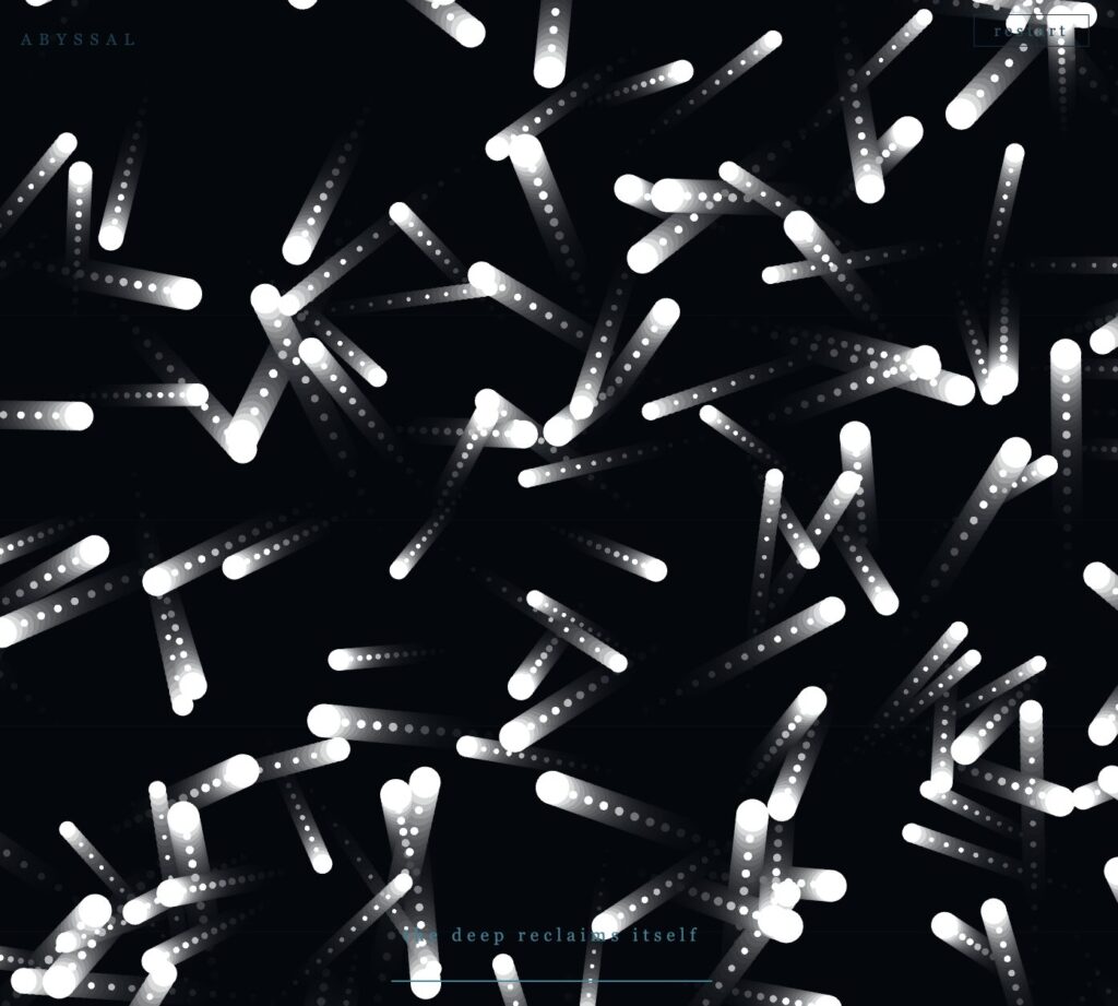
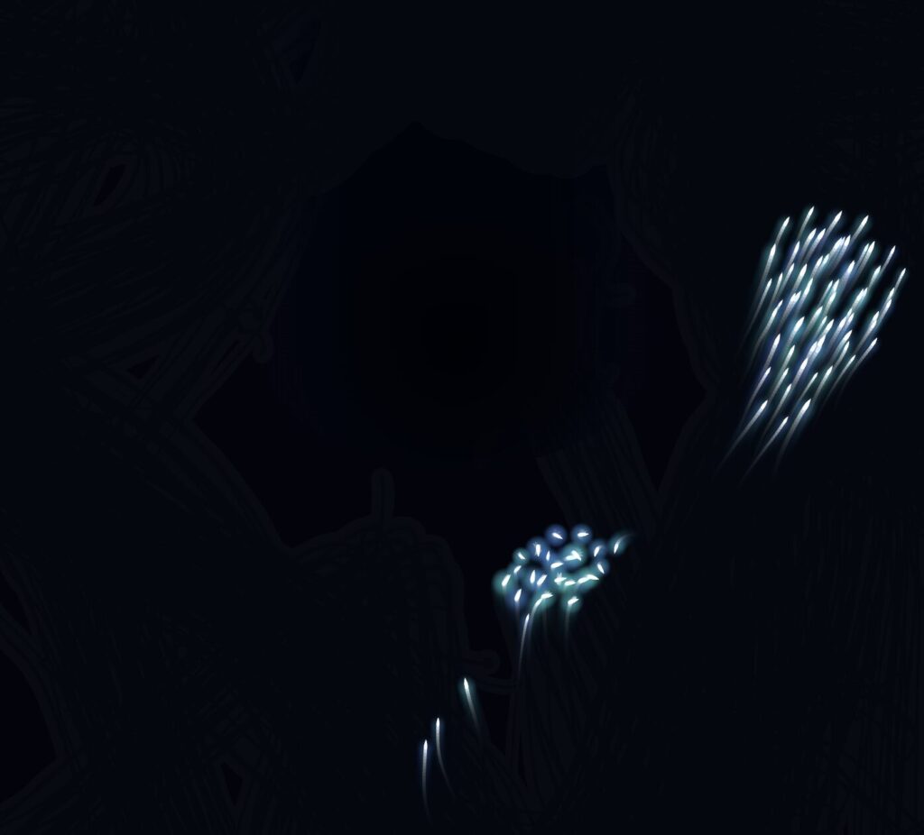
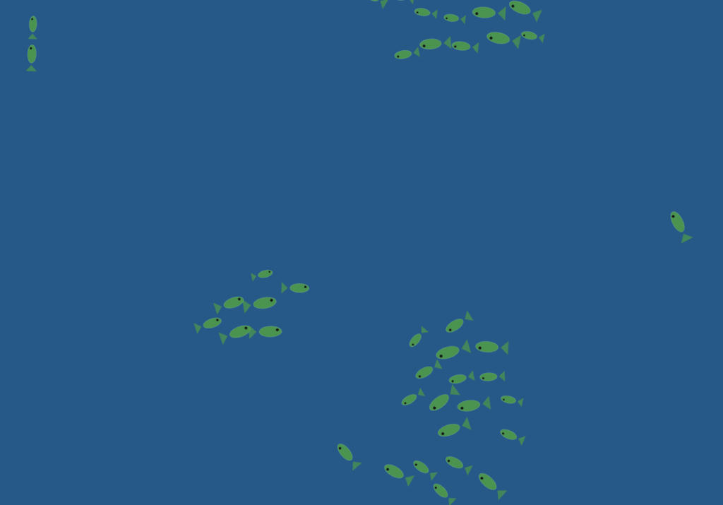
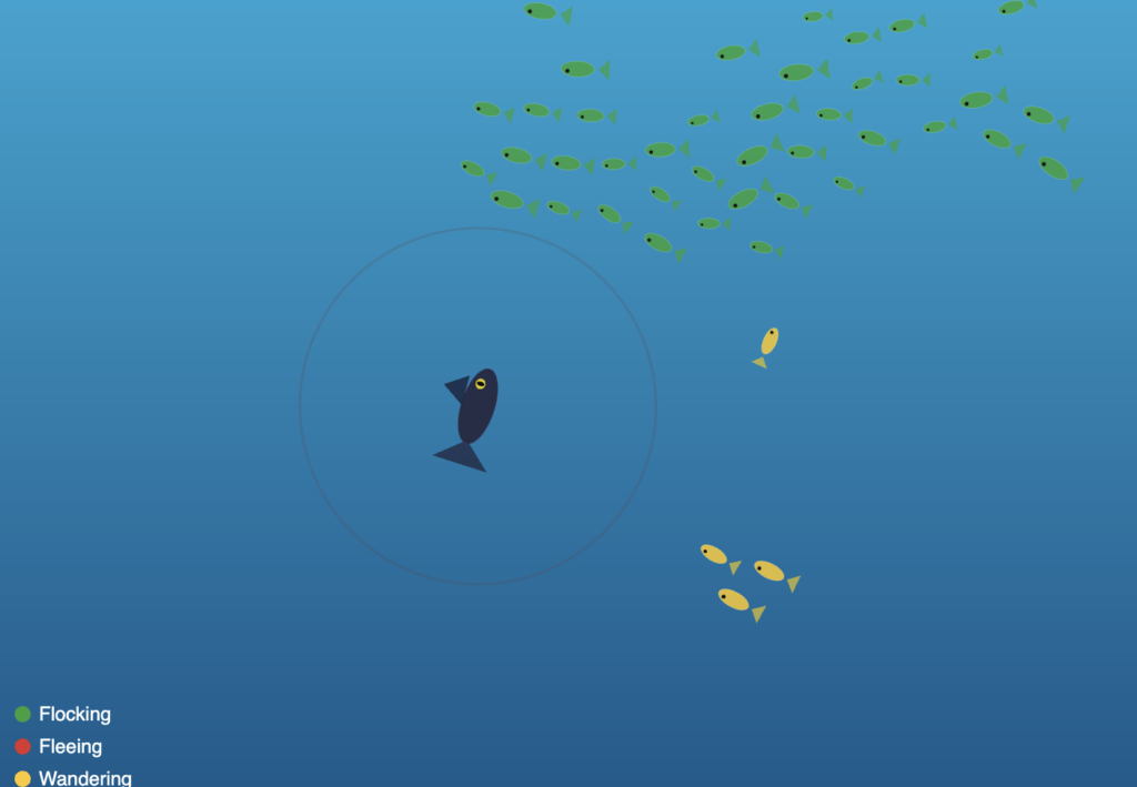
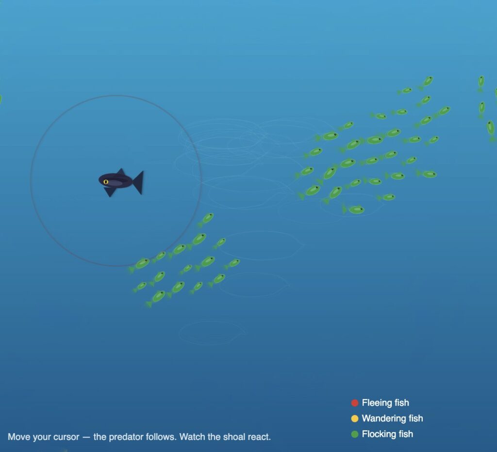
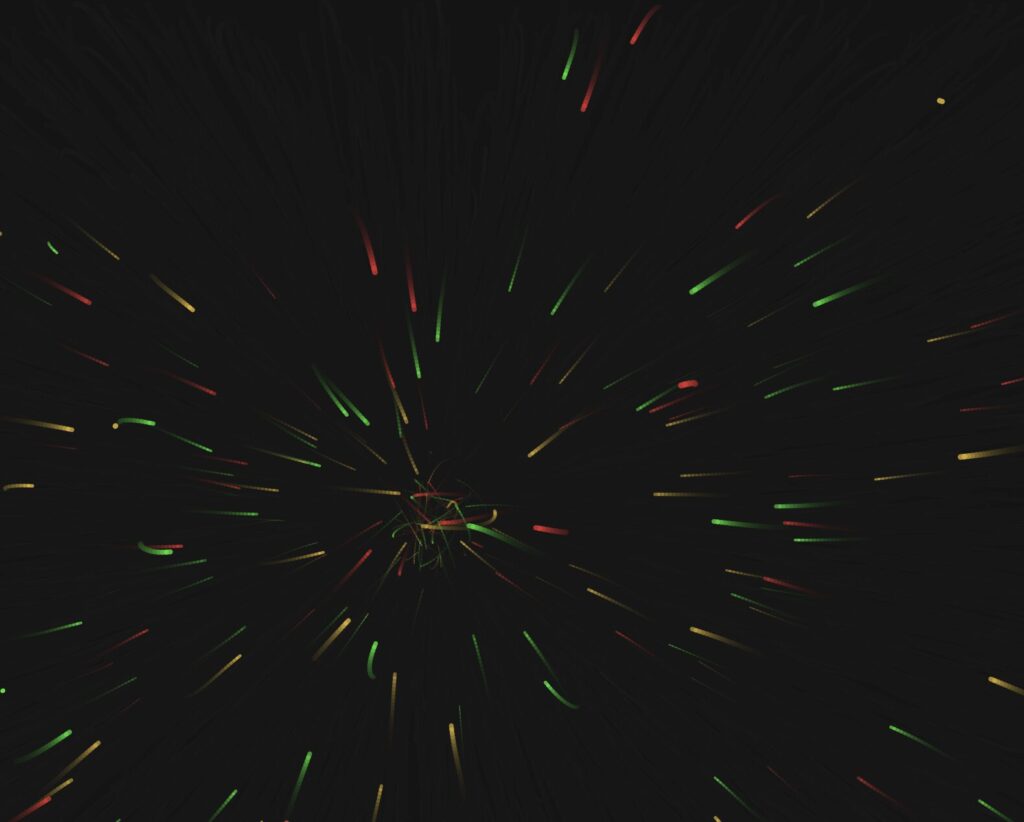
The screenshots below were captured during developmental stages. They show how the system evolved from a basic noise-driven particle experiment with no symbol geometry, to a single-symbol prototype, to the full multi-mode system with all three Adinkra symbols, their individual color palettes, and the orbital travelT motion system in place. Each stage informed the decisions that shaped the final version.


The Three Outputs

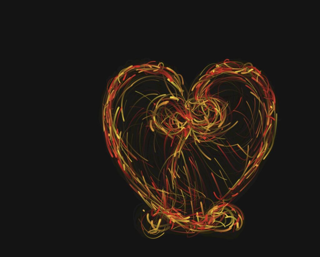
The three exported images below were captured during the warmup phase of each mode — when the particles are moving slowly enough for the symbol to read clearly, but with enough energy that the trails and motion feel alive rather than static. Each image was saved using the S key at the moment the composition felt most balanced.

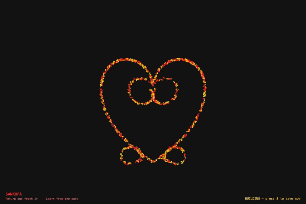
Output 1 — Sankofa. Red and gold particles tracing the abstract heart body with the V-extension inner spirals nestled at the top and the two outward bottom spirals flanking the pointed tip.

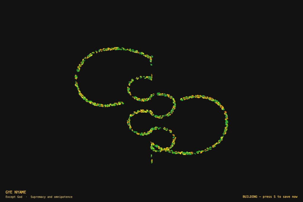
Output 2 — Gye Nyame. Gold and green particles tracing the alternating C-knob spine and the two diagonal fishhook arms — upper-left hooking down, lower-right hooking up.

Output 3 — Adinkrahene. Three concentric rings in red (inner), gold (middle), and green (outer), mirroring the Ghanaian flag’s stripes. A radiator streak is visible crossing all three rings outward from the center.


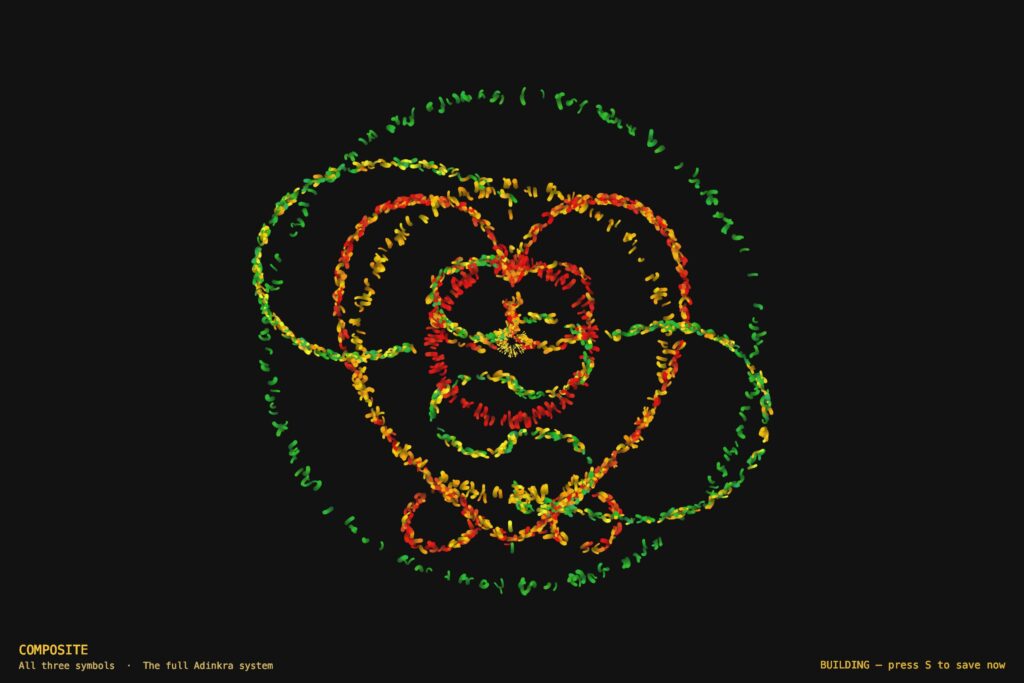
Output 4 — Composite Image.

Sketch

Video Documentation

The video below demonstrates all four modes of the system in sequence. Modes are switched live using the keyboard.


Reflection

What Changed From the Progress Version

The progress version worked mechanically but had no conceptual anchor. Four modes of maze navigation — functional, but nothing to say.

Rebuilding around Adinkra symbols gave the project a reason to exist. These symbols are not decorations. They are compressed philosophy from my own culture. Making them the invisible architecture of a particle system felt like engaging with that tradition rather than just referencing it.

What Worked

The invisible symbol approach is more legible than expected. After twenty to thirty seconds, the shape reads clearly from particle density and trail patterns alone — no drawn outline needed.

The flag color assignment has real logic behind it. Adinkrahene’s rings being red, gold, and green — mirroring the flag’s stripes radiating outward — is not arbitrary, which makes it easy to write about honestly.

The travelT motion system was the most important technical decision. Before it, particles jittered statically near the outline. After it, they flow continuously along the symbol in both directions. That change made the whole system feel alive.

The warmup ramp solved the screenshot problem cleanly. The first ten seconds of each mode are naturally the best window — no extra configuration, just press S.

What Was Hard

Getting the symbol geometry right took the longest. Both Sankofa and Gye Nyame are complex shapes that resist clean Bézier approximation. Several versions were discarded. The hardest part was not the math — it was building enough visual understanding of each symbol to know when the approximation was close enough.

Gye Nyame required understanding that its two diagonal arms are a 180-degree rotation of each other, not a mirror reflection. That asymmetry — the chirality — had to be correct in the coordinates before the symbol read as itself.

The closest-point lookup was a performance problem. Running Bézier math per particle per frame at 1,100 particles tanks the frame rate. The precomputed LUT — sampling the outline once at startup, doing a flat array search every frame — fixed it.

Plans for Future Improvement

Mouse interaction — clicking creates a temporary repulsion force, particles push away then return. Sankofa’s meaning becomes physically interactive.

Audio reactivity — microphone amplitude mapped to speedMult so the symbols respond to sound. The global speed multiplier is already in place; connecting an audio input would be a small change.

More symbols — Dwennimmen (strength and humility) and Funtunfunefu (democracy) are both geometrically interesting and personally meaningful. New LUT geometry, same motion system.

Mode transitions — a dissolve instead of a hard cut to black. Old particles fade out while new ones spawn in, suggesting the symbols share the same world.

References

Adinkra — Cultural Sources

Rattray, R. S. (1927). Religion and Art in Ashanti. Oxford: Clarendon Press.

Willis, W. B. (1998). The Adinkra Dictionary. The Pyramid Complex.

Adinkra Symbols of West Africa. adinkrasymbols.org

Eglash, R., Bennett, A., Lachney, M., & Bulley, E. Adinkra Spirals. csdt.org/culture/adinkra/spirals.html — geometric analysis of logarithmic spirals in Adinkra symbols.

Technical Resources

Shiffman, D. (2024). The Nature of Code, 2nd Edition. natureofcode.com

p5.js Reference Documentation. p5js.org/reference

The Coding Train — Daniel Shiffman. Introduction Videos I.2–I.4. thecodingtrain.com

Visual Inspirations

Ghanaian Kente cloth — the red, gold, green, and black palette comes directly from Kente patterns and the national flag.

AI Disclosure

AI tools (Claude, Anthropic) were used for debugging geometry and performance issues, identifying the LUT optimization, reviewing force application logic, and assisting with drafting this documentation. All creative decisions and final code were done by me.

Buernortey – Assignment 7

Video of Inspiration

Why I Chose This Visual

At teamLab, visitors could pick up a pencil drawing of a butterfly, flower, or lizard, color it in, and slide it under a scanner. Seconds later, their drawing appeared on the floor, glowing, animated, and moving freely through all the other visitors’ creations.

I chose a butterfly pencil drawing and colored it yellow. Watching that specific butterfly appear on the floor and drift between everyone else’s drawings was unlike anything else in the installation. Every other room at teamLab was something you walked through. This one was something you contributed to. The floor felt like a collective painting that no single person made, a shared canvas where hundreds of people’s choices all coexisted at once. That feeling is what I wanted to recreate in code.

The Sketch

The sketch shows a yellow butterfly entering from the left edge of a glowing, color-shifting floor, drifting organically through a crowd of colored creatures, flowers, fish, lizards, and swirling light forms, all wandering autonomously in every direction.

My creative twist: In the real installation, the floor was one continuous shared projection and you had no control over where your drawing went. In my version, I gave each creature a fully hand-coded personality — fish have tails, dorsal fins, and an eye with a pupil; lizards have four legs, a wagging tail, and a snout; flowers rotate their petals slowly as they drift; swirls pulse with orbiting circles. Each type is drawn entirely with p5’s shape functions — no images. The background also constantly shifts between deep blue, purple, magenta, and teal gradients, with large soft blobs of colored light drifting across the floor to simulate the ambient projected pools of color that filled the room at teamLab.

Code I’m Proud Of

The two pieces of code I’m most proud of are the wander steering system and the bezier butterfly wings.

Every creature , including the butterfly, uses wander steering. Instead of moving in straight lines or bouncing off walls, each creature accumulates tiny random velocity nudges every frame. This produces natural, unpredictable paths that feel alive rather than mechanical:

// Wander: nudge direction slightly each frame
this.vx += random(-0.04, 0.04);
this.vy += random(-0.03, 0.03);

// Speed cap — keep drift gentle
if (abs(this.vx) > this.spd)       this.vx *= 0.97;
if (abs(this.vy) > this.spd * 0.5) this.vy *= 0.97;

// Soft vertical boundaries — no hard bouncing
if (this.y < height * 0.32) this.vy += 0.05;
if (this.y > height * 0.97) this.vy -= 0.05;

The butterfly wings use bezierVertex() : four control points per wing half, mirrored on both sides, with a sin() oscillation scaling the wing width to simulate flapping:

// Upper wing — bezier shape
fill(yw);
beginShape();
vertex(0, -s * 0.10);
bezierVertex(s*0.22, -s*0.85, s*0.95, -s*0.72, s*0.82, -s*0.08);
bezierVertex(s*0.48,  s*0.12, s*0.10,  s*0.04, 0,      -s*0.10);
endShape(CLOSE);

// Flap: scales wing width using sin() — makes wings open and close
scale(side * (1 + flap * 0.28), 1);


Milestones and Challenges

Drawing every creature in pure code: The first decision was to use no images at all. Every flower petal, fish tail, lizard leg, and butterfly wing is drawn with p5’s shape functions. This took the most time but felt true to the spirit of the installation: simple outlines brought to life by color and motion.

Getting the butterfly wings right:  The bezier control points for the wings required a lot of manual tuning. The upper and lower wing have different shapes and different amber tones, and the mirroring had to be handled carefully using scale(-1, 1) inside a push()/pop() block so the two sides stayed symmetrical.

The shifting background: The original dark background made everything look dim. The solution was a background that draws a full-height gradient every frame, blending between three RGB color stops that slowly transition through a series of blue, purple, and magenta palettes. Five large drifting light blobs were added on top to simulate the ambient projected pools of color from the real installation.

Challenge, Perspective on a 2D canvas: The real teamLab floor had true projection-mapped depth — creatures far away appeared smaller and more faded. In 2D p5.js this had to be faked with a vanishing-point grid where lines converge on a horizon point, horizontal lines spaced using a power curve for perspective, and a warm glow rising from the bottom of the frame. It reads as a floor but is not true 3D.

Challenge:  When all the creatures were first added at similar speeds, the result looked like a screensaver. The fix was differentiating speed ranges per type, swirls drift slowly, fish move quicker, and the yellow butterfly moves faster and more directionally than everything else. That hierarchy gives the butterfly a sense of purpose and navigation rather than just floating.

Reflection and Ideas for Future Work

The most surprising part of building this was how much of the experience at teamLab came from pacing rather than visuals. The gentleness, nothing crashing, nothing disappearing abruptly, everything drifting, was harder to code than any of the shapes. Getting the wander steering to feel calm required many small adjustments to speed caps and boundary forces.

What is still missing most is convincing depth. The real floor had a spatial quality where distance was clearly readable. My version is flat, and that flatness makes it feel more like a simulation than an environment.

Ideas for future versions:

  • Use p5’s WEBGL mode so creatures scale smaller as they move toward the horizon, matching real perspective depth
  • Add a coloring step and let the user pick a color for their butterfly before it enters the floor
  • Implement Boids flocking so similar creatures occasionally cluster and drift together, which happened naturally at teamLab
  • Add ambient sound, low electronic tones and soft wing-flutter audio, to complete the immersion

Buernortey – Midterm Progress

Midterm Project Overview

This project expands on my assignment 3 project, where particles navigated a maze using goal attraction, wall repulsion, and turbulence. The midterm version adds multiple modes to explore different particle behaviors: refined maze navigation, free-flow turbulence, oscillating attractors, and dual attractors. The aim is to create diverse visual outputs and experiment with particle interactions, motion patterns, and color dynamics.

Implementation Details

The system now has a mode-based structure, allowing easy switching between behaviors using key presses (1–4). Each mode has its own settings for particle count, trail transparency, force strengths, and colors. Particles have variable sizes and colors, with trails rendered dynamically. Goals can be static, oscillating, or dual, depending on the mode.

Currently, walls are only implemented in Mode 1, the refined maze navigation mode. This is intentional for the progress version because Modes 2–4 are focused on exploring other behaviors, such as turbulence fields and moving attractors, without the influence of walls. Walls will be added to all modes in the final version to enhance particle interactions and visual complexity.

The reason for keeping the previous code is that the core particle and force mechanics are solid, so the current version builds on that foundation while adding more modes, dynamic goals, color variations, and adjustable parameters.

Key code highlights:

  • Mode system for switching between particle behaviors.

  • Particle class with forces: goal attraction, wall repulsion, and turbulence.

  • Dynamic goal movement in oscillating and dual-attractor modes.

  • Adjustable parameters for particle appearance, motion, and trail transparency.

  • Walls implemented in Mode 1, with plans to expand to all modes in the final version.

Progress

Base Code(Assignment 3):


Current state:

Mode changes with number: 1, 2, 3 and 4.

Reflection

The system is modular and flexible, making it easy to tweak parameters and add new behaviors. Next steps include creating more visually distinct modes, experimenting with more complex attractors or obstacles, and improving color and trail effects to produce final high-resolution outputs suitable for A3 prints.

References

Buernortey – Assignment 4

Concept and Inspiration

This sketch is inspired by my high school physics experiments with simple harmonic motion, especially spring–mass systems. In those experiments, we measured displacement and time as a mass oscillated back and forth, but the motion was mostly understood through formulas and graphs.

For this project, I wanted to recreate that experiment visually and interactively. Instead of only calculating values, my goal was to simulate the motion directly and allow parameters like amplitude, oscillation rate, and damping to be adjusted live. This turns the physics formula into something observable and explorable.

The final result is an interactive spring–mass simulation driven directly by the SHM equation.

Development Stages

Below are the main stages of how the sketch evolved:

Stage 1 — Basic Oscillation

Purpose: Test the SHM formula using a moving dot. This stage ensures the sine-based oscillation behaves as expected.

Stage 2 — Spring–Mass Visualization

Purpose: Represent the physics lab setup visually. A zig-zag spring connects the mass to equilibrium, giving a realistic spring–mass system.

Stage 3 — Interactive SHM with Damping

Purpose: Add interactivity and more realistic physics. Users can control amplitude, oscillation rate, and damping. Motion trail shows past displacement.

Code Highlight

The most important line in the final sketch is:

let x = equilibrium + amplitude * sin(angle) * exp(-damping * time);

This combines harmonic oscillation(sin()), displacement scaling (amplitude), and exponential decay (damping). It directly translates the physics model into animation behavior.

Final Sketch

In the final version, the sketch became fully interactive. Users can adjust sliders to control amplitude, oscillation rate, and damping, and a motion trail shows the displacement history over time. The spring–mass system is visualized clearly, and all variable names are stable to avoid conflicts with p5.js reserved functions.

Challenges Encountered

During development, the first connector looked more like a rope than a spring, so I had to adjust the zig-zag design to make it visually accurate. Balancing the damping values took several tests to ensure the motion was realistic but not too quick to stop. Slider ranges also needed careful tuning to prevent unstable or jittery motion. Additionally, the variable originally named speed conflicted with a reserved p5.js function, requiring a rename to rate. Each challenge was solved through iterative testing and visual adjustments to maintain smooth and accurate motion.

Reflection and Future Improvements

This project helped me understand simple harmonic motion more intuitively than through static formulas. Seeing the oscillation respond to parameter changes in real time made the relationships between amplitude, speed, and damping much clearer. For future improvements, I would add a live sine graph alongside the spring, a toggle to switch to a pendulum mode, multiple coupled springs to simulate more complex systems, and data readouts similar to a virtual lab tool to record measurements and analyze motion quantitatively.

Buernortey Buer – Assignment 3

Concept and Inspiration

This project simulates particles moving through a maze using forces rather than bouncing off walls. Each particle is pulled toward a target point but pushed away by invisible walls shaped like rectangles. A gentle random force based on Perlin noise makes their movement look natural and smooth. I was inspired by sci-fi movies like Tron and by art that uses flowing patterns. The goal was to create flowing, energy-like paths that happen naturally from how the forces work together, not from fixed paths.

Code Organization and Naming

The code is organized into clear components: a Particle class manages position, velocity, acceleration, and trail rendering; a Wall class defines rectangular obstacles; and dedicated functions handle forces (applyGoalAttraction(), applyWallRepulsion(), and applyTurbulence()). This separation keeps the program modular and readable. Variable and function names are descriptive — like goalStrength, wallRepelStrength, and applyWallRepulsion — to make the code’s purpose immediately clear without confusion.

Code Highlights and Comments

I’m particularly proud of the wall repulsion system, which calculates the closest point on each wall rectangle to the particle and applies a smoothly scaled repulsion force. This method avoids abrupt collisions, allowing particles to gently slide away from walls rather than bouncing harshly. As a result, the particle trails form elegant, curved paths that reveal the flow of forces shaping their motion. The code is carefully commented, especially in the tricky parts like the closest-point calculation and force scaling, to clearly explain the math and logic behind this smooth, natural movement.

// push particles away from rectangles
function applyWallRepulsion(p) {
  for (let w of walls) {

    // find closest point on wall rectangle
    let closestX = constrain(p.pos.x, w.x, w.x + w.w);
    let closestY = constrain(p.pos.y, w.y, w.y + w.h);

    let closestPoint = createVector(closestX, closestY);

    // vector from wall to particle
    let diff = p5.Vector.sub(p.pos, closestPoint);
    let d = diff.mag();

    // only repel if within influence distance
    if (d < 40 && d > 0) {
      diff.normalize();

      // closer = stronger push
      let strength = wallRepelStrength / d;
      diff.mult(strength);

      p.applyForce(diff);
    }
  }
}


Embedded Sketch

Milestones and Challenges

I started by making particles move toward a goal and then added trails so you could see their paths. Adding turbulence made the movement look more natural and interesting. Creating walls and figuring out how to push particles away smoothly was hard but important for realistic motion. I had to try different force strengths because if the push was too strong, particles got stuck, and if it was too weak, they went through walls. Using a semi-transparent background helped the trails build up visually, and limiting particle speed kept the motion steady.

Reflection and Future Work

This project helped me better understand how multiple forces interact to create complex, emergent movement. Compared to the simpler exercises we did in class, this system feels more full and alive because the forces come from the environment, not just between particles. It was exciting to see invisible forces made visible through the trails the particles leave. In the future, I want to add things like walls you can change with the mouse, more goals for particles to follow, moving obstacles, colors that change based on force, and sliders to adjust settings while the program runs.

Buernortey Buer – Assignment 2

Simulating the Free Movement of Clouds

Concept

This assignment is inspired by a scene from my favorite anime “Naruto” in which a character looks up at the sky and expresses a desire to be like the clouds, moving freely without worry and simply following the wind. That idea of effortless movement and quiet reflection became the foundation for this simulation.

To connect this idea to real world motion, I found a video online of clouds slowly drifting across the sky and used it as a reference. Rather than focusing on the visual appearance of the clouds, the emphasis was placed on replicating their movement. The behavior in the sketch is controlled entirely through acceleration, allowing motion to emerge naturally from wind like forces over time. While the clouds all move in the same general direction, small variations in their movement prevent the motion from feeling uniform or repetitive.

The intention of this assignment is to recreate the calm experience of watching clouds pass by, capturing a feeling of flow and freedom through motion rather than visual detail.

Code Highlight

A key part of the simulation is how wind direction and strength are controlled using Perlin noise, which provides smooth and natural variation over time:

let baseWindAngle = PI; // base direction pointing leftwards
let noiseVariation = (noise(frameCount * 0.003 + this.offset) - 0.5) * (PI / 6);
let windAngle = baseWindAngle + noiseVariation;
let wind = p5.Vector.fromAngle(windAngle);
wind.setMag(0.05);
this.acc.add(wind);

Here, each cloud experiences a base wind force pushing it leftwards (PI radians), with subtle angle variations added by noise for a natural, organic drift.

Embedded Sketch

Reflection and Future Ideas

This project helped me understand how motion driven entirely by acceleration can create lifelike, organic behavior without directly manipulating position or velocity. Using Perlin noise to vary the wind direction over time introduces natural unpredictability, allowing each cloud to move with variation rather than uniform motion. Watching the clouds drift smoothly across the canvas feels calm and meditative, similar to observing real clouds moving through the sky.

In the future, this system could be expanded by allowing clouds to interact with one another, respond to changing environmental conditions, or evolve based on different wind patterns. Small visual enhancements, such as lighting changes or atmospheric shifts, could also be explored while keeping the movement rooted in physics-based rules. Overall, this simulation captures a quiet moment of nature’s flow and reflects the peaceful experience of simply watching clouds pass by.

Buernortey – Assignment 1

Concept

For this project, I created a random walker that moves using dynamic probabilities instead of fixed directions. At every step, the walker makes a decision: it has a 50% chance to move toward the mouse and a 50% chance to move in a random direction. This creates motion that sometimes feels intentional and sometimes unpredictable.

To connect motion to another medium, I mapped movement into color by letting the walker walk through HSB color space. As the walker moves, its hue slowly shifts, leaving a trail of changing colors. This makes the motion visible not only through position, but also through color.

Code Highlight

The part I am most proud of is the simple probability rule that controls the walker’s behavior:

// 50% chance: move toward mouse
if (random(1) < 0.5) {
  let target = createVector(mouseX, mouseY);
  let dir = p5.Vector.sub(target, pos);
  dir.setMag(step);
  pos.add(dir);
} 
// 50% chance: random move
else {
  let angle = random(TWO_PI);
  pos.x += cos(angle) * step;
  pos.y += sin(angle) * step;
}

With only one small decision, the system creates two very different behaviors: attraction and randomness. This balance makes the motion feel alive without being complicated.

Embedded Sketch

Reflection and Future Work

This project showed me how simple rules can create expressive motion. Even with only two possible choices, the walker feels responsive and unpredictable at the same time. I also liked how color helped reveal the path and rhythm of the movement.

In the future, I would like to change the probability based on the distance to the mouse so the attraction becomes stronger or weaker depending on position. I would also like to add multiple walkers with different behaviors and experiment with Gaussian step sizes to create smoother motion. Another idea is to map movement to sound, such as pitch or stereo pan, instead of color.

Overall, this project helped me understand how probability and interaction can shape motion in simple but interesting ways.