Project Overview
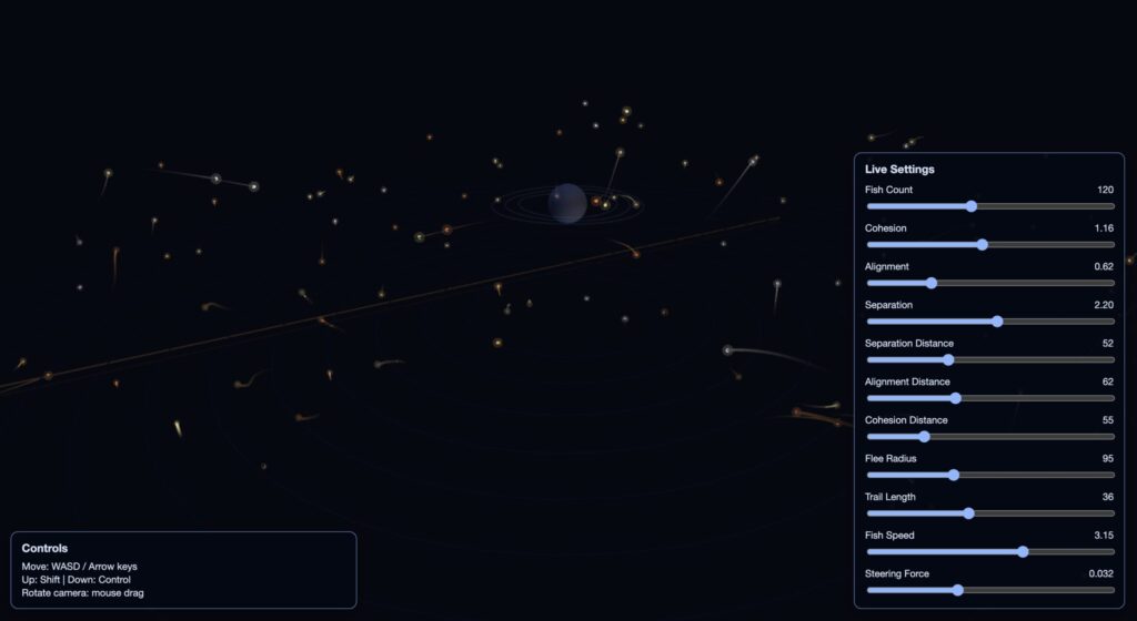
This project explores a hand-tracked 3D interactive environment where a topology grid and boids react to user gestures.
The core concept combines three ideas I enjoyed most during the course: simple rule-based systems, satisfying emergent movement, and 3D simulation.
The final direction uses open-palm and clenched-fist gestures to attract/repel boids while the hand also influences a dynamic topology surface.
The design goal was to keep the visual language minimal and angular: mesh-line hands, a dot-based topology map, and color-coded boid states.
Instead of using gestures to rotate the world, gestures directly affect behavior inside the world.
Inspiration
I was initially unsure where to start, so I researched interactive installations and reflected on previous class work.
The project direction became clearer after revisiting hand recognition from our ml5.js session and combining it with topology and boids.
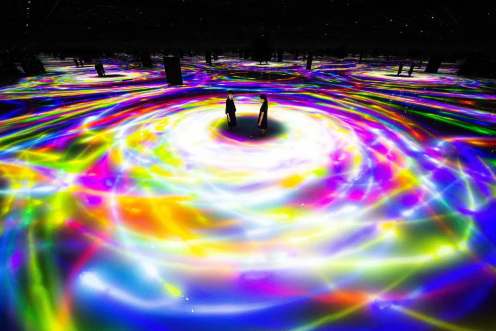
Pulse Topology by Atelier Lozano-Hemmer inspired the topology-grid idea.

Pulse Island I by the same artist inspired a calmer movement pacing.

Gesture examples from the Hand-Tracked Particle Simulator helped frame interaction possibilities, but also clarified what not to do
(gesture as pure camera/object rotation felt less natural for this project).


Seeing virtual hands in 3D (similar to headset experiences) became an important target for immersion.


Video Documentation
Final interaction and visual output demo:
Github Repository:
https://github.com/ssl9619/Decoding-Nature-Hand-Gesture-Final-Project/
Implementation Details
Milestone 1: ml5.js hand tracking in 3D (flat result)

First attempt used ml5.js with depth estimation to push landmarks in z-space.
While it partially worked for forward/back movement, rotation and depth consistency were limited.
Milestone 2: Switching to MediaPipe Hand Landmarker

I moved to MediaPipe Hand Landmarker for more reliable xyz output. This enabled more convincing 3D hand behavior while retaining similar landmark structure.
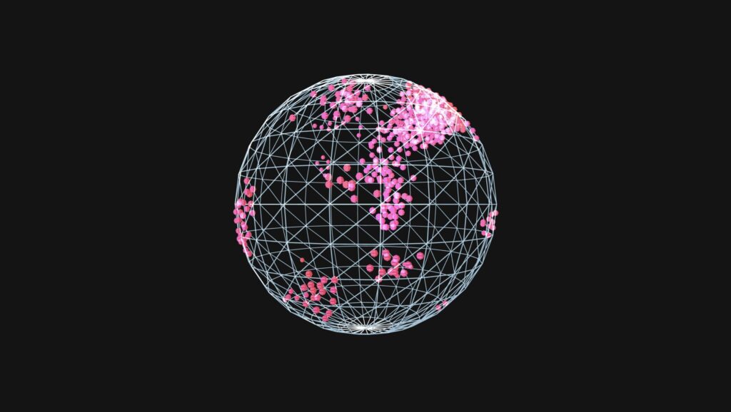
Milestone 3: Topology grid and shader optimization

The topology points are mapped to simplex noise in shader space. Height is mapped from noise values (-1 to 1), and brightness changes with height.
A shader implementation was required to resolve performance issues from CPU-heavy updates.
Milestone 4: Combining hand interaction and topology response

After integration, hand positions created indentation-like effects in the topology map (similar to pin-screen behavior).
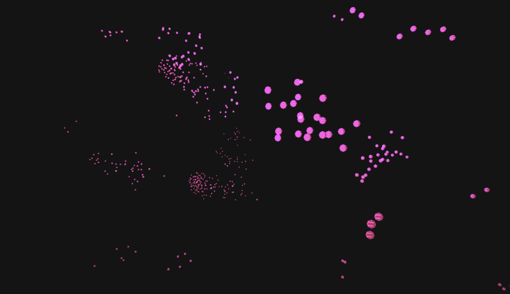
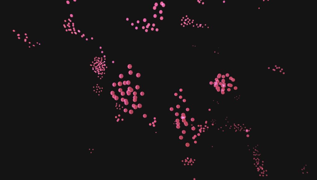
Milestone 5: Adding boids interaction logic


Boids were integrated as a behavior system driven by gesture state and local interactions.
Final tuning focused on attract/repel responsiveness and state transitions.
Milestone 6: Hand Gesture recognition


For this milestone I focused on mapping hand poses into reliable interaction modes.
An open palm triggers attraction/follow behavior, while a clenched fist triggers repel/escape behavior.
The main challenge was keeping gesture classification stable frame-to-frame so boids did not rapidly flicker between states.
Milestone 7: Creating a design for the hand
![]()


I tried several visual designs for the hand and ultimately returned to a style close to the original skeleton, but built from 3D forms.
First, I attempted an outline-style hand, but I was not satisfied with the overall look.
Second, I tried ellipses with a billboard approach, but visibility and depth readability were weak.
Finally, I switched to spheres and cylinders with mesh lines. It is not perfect, but it gave the best balance of clarity and style among the three approaches, and it remains an area for future improvement.
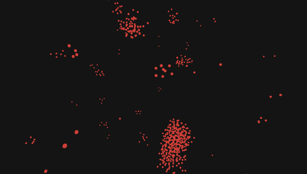
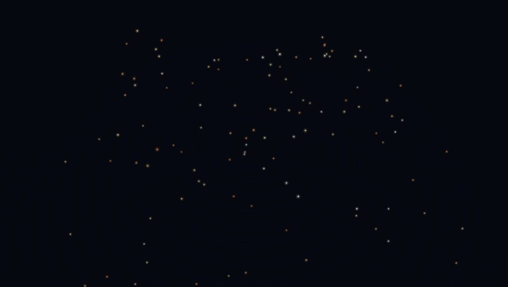
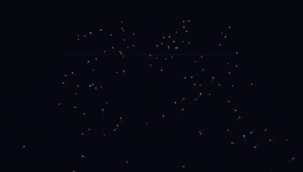
Boids Behavior and State Machine
- Wander (yellow): default movement state.
- Follow (blue): triggered by open palm when boids are within interaction distance.
- Escape (red): triggered by clenched fist; boids return to wander after enough distance.
- Contagion behavior: wandering can spread to nearby boids after prolonged following.
- Close-range behavior: boids can orbit around the hand during attraction.

Hand Recognition Pipeline
The project started with ml5.js but switched to MediaPipe for stronger 3D landmark behavior.
AI assistance was used for migration and integration details.

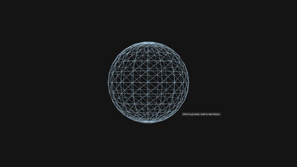
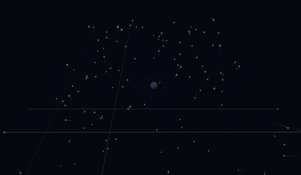
Topology Grid
- Simplex noise drives surface displacement over time.
- Point brightness changes according to displacement height.
- Shader implementation improved runtime performance significantly.
- Grid can be circular by default, with a boolean option for rectangular mode.
3D Rendering and Navigation
- Rendering uses WEBGL canvas.
orbitControl()allows scene inspection and confirms true 3D behavior.
Code Highlights
Highlight 1: Orientation Gizmo Drawing
function drawOrientationGizmo(center, orientation) {
  const right = p5.Vector.mult(orientation.right, GIZMO_SCALE);
  const up = p5.Vector.mult(orientation.up, GIZMO_SCALE);
  const normal = p5.Vector.mult(orientation.normal, GIZMO_SCALE);

  // For some reason (unknown to man) when commenting this out the topology grid stops working
  // so instead I just made strokeWeight(0) and wont ask any more questions
  strokeWeight(0);
  stroke(255, 90, 90);
  line(center.x, center.y, center.z, center.x + right.x, center.y + right.y, center.z + right.z);
  stroke(90, 255, 120);
  line(center.x, center.y, center.z, center.x + up.x, center.y + up.y, center.z + up.z);
  stroke(90, 150, 255);
  line(center.x, center.y, center.z, center.x + normal.x, center.y + normal.y, center.z + normal.z);
}
This is a highlight for all the wrong reasons. So really, its more of a lowlight. When changing from ml5.js to MediaPipe Hand Landmarker I relied heavily on AI to switch for me given it was my first time. In doing so it created this function. All it does is shows 3 lines perpendicular to each other with colors for each axis x,y,z and its at the center of the hand. Why? Not sure, but I tried removing the function from the update loop and suddenly the topology grid would stop working. Weird I thought, I’ll try just commenting out the lines relating to drawing the lines but I had the same issue. I realized at this point that perhaps its due to the topology grid being rendered using a shader and I didn’t really understand how that worked. I thought to myself, I don’t know exaclty why it doesn’t work, and I don’t want to find out why, because I don’t have much time or patience to do so. Lazily, I set the strokeWeight to zero and moved on.
Highlight 2: updateState() in boids3d.js
updateState(connectedWanderCount, mode, target) {
  const config = this.config;
  const stateConfig = config.state;
  const distToTarget = p5.Vector.dist(this.pos, target);

  if (this.wanderCooldown > 0) {
    this.wanderCooldown -= 1;
  }

  if (mode === "repel") {
    if (this.state !== "escape" && distToTarget < stateConfig.escapeTriggerDistance) {
      this.enterEscapeState();
    }
    if (this.state === "escape") {
      if (distToTarget >= stateConfig.escapeToWanderDistance) {
        this.enterWanderState();
      }
      return;
    }
  } else if (this.state === "escape") {
    this.enterFollowState();
  }

  if (this.state === "wander") {
    this.stateTimer += 1;
    this.wanderDurationLeft -= 1;
    if (this.wanderDurationLeft <= 0) {
      this.enterFollowState();
    }
    return;
  }

  this.stateTimer += 1;
  if (this.stateTimer < stateConfig.followBeforeWanderFrames || this.wanderCooldown > 0) {
    return;
  }

  const chance =
    stateConfig.baseWanderChancePerFrame +
    connectedWanderCount * stateConfig.neighborWanderChanceBonus;
  const cappedChance = min(chance, stateConfig.maxWanderChancePerFrame);
  if (random() < cappedChance) {
    this.enterWanderState();
  }
}
The boids and the hands are perhaps my favourite part of the simulation and in large part due to their interaction with each other. Central to their interaction is this state machine which determines whether a boid should wander, escape, or follow.
Reflection
I am very happy with the final result and how the interaction reads visually.
The topology-grid performance issue was resolved through shader-based optimization, while boids still have unresolved performance costs in denser scenarios.
One known bug remains: if the simulation starts while the palm is already open, boid state updates can behave unexpectedly until performing a clench-then-open reset.
References
- ml5.js documentation
- The Nature of Code (Daniel Shiffman)
- MediaPipe Hand Landmarker documentation
- Ultraleap documentation
- Hand landmark position/index reference image
- Hand-Tracked Particle Simulator (GitHub)
- SpaceX gesture-based design video (2013)
- Atelier Lozano-Hemmer – Pulse Topology
- Atelier Lozano-Hemmer – Pulse Island
AI Disclosure: AI assistance was used for shader-based topology optimization and migration from ml5.js hand tracking to MediaPipe Hand Landmarker integration.


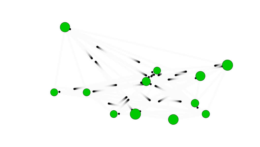
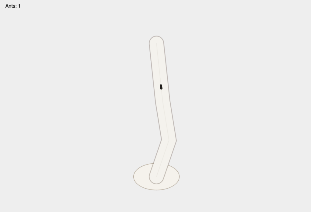 I started with one ant following one path to verify that seek and basic path following were working correctly.
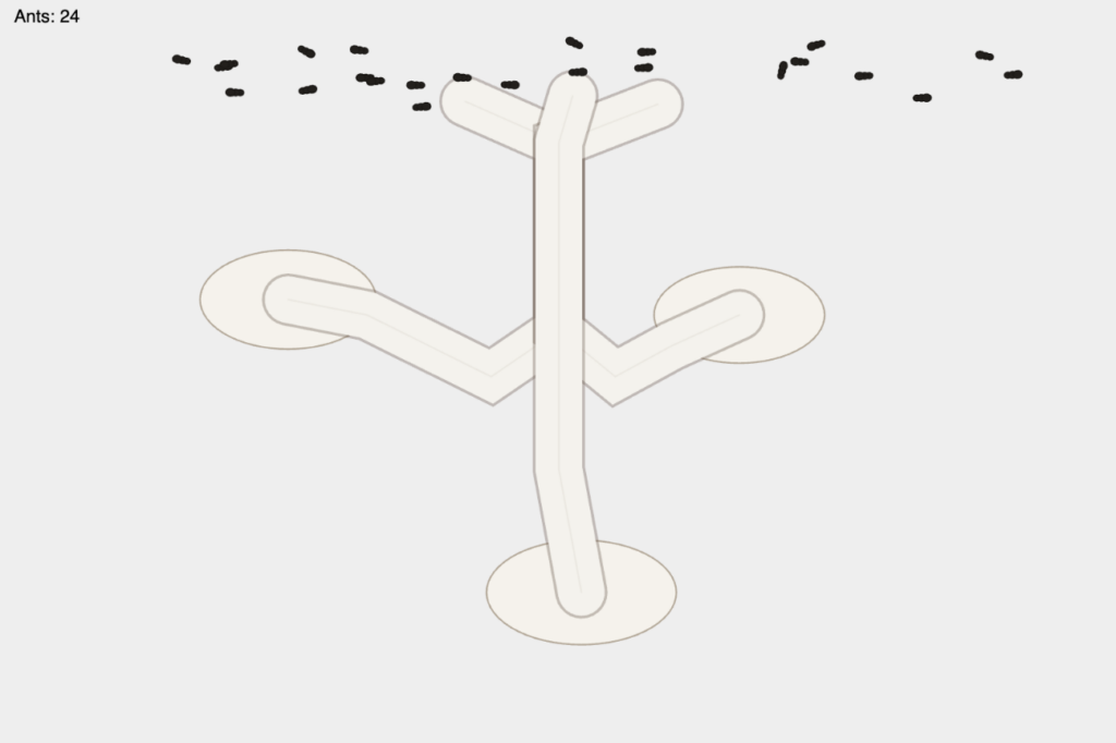

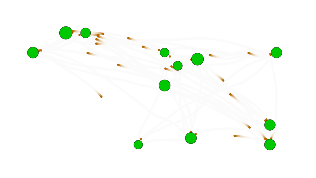
 At this point I created the Mountain class, it would be different sizes and I just had it spawn randomly around the canvas at this point and I could change how many would spawn. As you can see at this point I didn’t implement the avoidance as you can see by the trail of one bird at the bottom that phased through the mountain.