There’s something genuinely strange about watching a crowd of autonomous agents share a canvas.
That’s the question behind DRIFT: what happens when you put three radically different vehicle archetypes into the same space, give each one its own agenda, and just let physics run?
The starting point was Craig Reynolds’ foundational work on steering behaviors: seek, flee, separation, alignment, cohesion. Those behaviors are well-documented and well-taught. The challenge I set for myself was to use them as raw material for something that reads more like an ecosystem than a demo.
I ended up with three vehicle types:
Seekers chase a moving attractor that is basically a signal that traces a path across the canvas. They leave luminous trails and pulse as they move.
Drifters ignore the signal entirely. They flock through alignment, cohesion, and separation. and wander using noise.
Ghosts flee. They push away from the signal and from the combined mass of every other vehicle in the scene. They end up haunting the edges of the canvas.
The signal itself moves on a parametric Lissajous curve, so it sweeps the canvas continuously without any user input required.
The Ghost’s `applyBehaviors` method is the piece I find most satisfying. The rule sounds simple — flee everything — but the implementation has a specific texture to it.
javascript
applyBehaviors(signal, allVehicles) {
let fleeSignal = this.flee(signal, 220);
let fleeCrowd = createVector(0, 0);

for (let v of allVehicles) {
fleeCrowd.add(this.flee(v.pos, 90));
}

let w = this.wander(1.2);

fleeSignal.mult(2.0);
fleeCrowd.mult(0.8);
w.mult(0.9);

this.applyForce(fleeSignal);
this.applyForce(fleeCrowd);
this.applyForce(w);
}
What I like here is that `fleeCrowd` is an accumulated vector. For every seeker and drifter on the canvas, the ghost computes a flee force and adds them all together. The result is that the ghost reads the density of the crowd. A ghost near a tight cluster of drifters gets a much stronger push than one near a single seeker. It behaves like a pressure system.
The wander force on top of that means no two ghosts trace the same path even under identical starting conditions. The noise field shifts slowly over time, so the wandering feels natural.
The wander method from the base `Vehicle` class handles this:
Getting the ghost behavior to feel ghostly rather than glitchy. The first version had ghosts with a flee radius too small, so they’d enter the crowd and then snap violently outward. Increasing the signal flee radius to 220 pixels and smoothing the crowd flee with accumulated vectors fixed the snapping.
The Lissajous signal path. My first instinct was to use `mouseX` and `mouseY` as the attractor, which is the standard approach for seek demos. The problem is that a static mouse produces boring convergence, everyone piles up on the target and sits there. A Lissajous curve gave the signal genuine sweep across the canvas, which keeps seekers in motion even after they’ve converged. The math is minimal:
function getSignalPos(t) {
let cx = width * 0.5;
let cy = height * 0.5;
let rx = width * 0.32;
let ry = height * 0.28;
return createVector(
cx + rx * sin(t * 0.41 + 0.6),
cy + ry * sin(t * 0.27)
);
The frequency ratio `0.41 / 0.27` is irrational enough that the path never perfectly repeats, so the sketch keeps shifting over long observation periods.
The three archetypes don’t interact across types in any interesting way. Seekers don’t react to drifters. Drifters don’t notice ghosts. The only cross-archetype behavior is the ghost’s crowd flee, which reads seeker and drifter positions as obstacles. A next version could introduce:
– Seekers that are temporarily distracted by passing drifter clusters, pulled off their trajectory before resuming the chase.
– The signal occasionally splitting into two attractors, creating competing factions among the seekers.
Visually, the grid underneath the simulation was meant to read as a city viewed from above, but it’s almost invisible after the first frame. Rendering it to a persistent background layer would strengthen that spatial metaphor.
For this assignment, I wanted to explore Autonomous Agents. I took inspiration from Craig Reynolds’ Steering Behaviors, specifically the idea that a vehicle can “perceive” its environment and make its own decisions.
My goal was to create a Living City. I designed a system of commuters or normal vehicles that dutifully follow a circular traffic path, and a Police car (the interceptor) controlled by the mouse. The commuters get out of the police car’s way as it approaches. The project explores the tension between order (Path Following) and chaos (Fleeing from danger).
Sketch
Process and Milestones
I started by building a multi-segment path. The biggest challenge here was the logic required to make the vehicles drive in a continuous loop. I used the Modulo operator (%) in my segment loop so that when a vehicle reaches the final point of the rectangle, its “next target” automatically resets to the first point.
At first, my vehicles were “shaking” as they tried to stay on the path. I realized they were reacting to where they are right now, which is always slightly off the line. I implemented Future Perception—the vehicle now calculates a “predict” vector 25 pixels ahead of its current position. By steering based on where it will be, the movement became much smoother and more life-like.
The most interesting part of the process was coding the transition between behaviors. I wrote a conditional check: if the distance to the Interceptor (mouse) is less than 120 pixels, the Commuter completely abandons its followPath logic and switches to flee. I also increased their maxSpeed during this state to simulate “panic.” Once the danger passes, they naturally drift back toward the road and resume their commute.
Code I’m Proud Of
I am particularly proud of the logic that allows the vehicle to choose the correct path segment. It doesn’t just look at one line; it scans every segment of the “city” to find the closest one, then projects a target slightly ahead of its “normal point” to ensure it keeps moving forward.
// Predictive Path Following logic
followPath(path) {
  // look into the future
  let predict = this.vel.copy().setMag(25);
  let futurePos = p5.Vector.add(this.pos, predict);

  let target = null;
  let worldRecord = 1000000;

  // scan all road segments for the closest point
  for (let i = 0; i < path.points.length; i++) {
    let a = path.points[i];
    let b = path.points[(i + 1) % path.points.length];
    let normalPoint = getNormalPoint(futurePos, a, b);

    // ... (boundary checks) ...

    let distance = p5.Vector.dist(futurePos, normalPoint);
    if (distance < worldRecord) {
      worldRecord = distance;
      // look 15 pixels ahead on the segment to stay in motion
      let dir = p5.Vector.sub(b, a).setMag(15);
      target = p5.Vector.add(normalPoint, dir);
    }
  }

  // steer only if we've drifted outside the lane
  if (worldRecord > path.radius) {
    this.seek(target);
  }
}
Reflection
This project shifted my perspective on coding movement. In previous assignments, we moved objects by changing their position; here, we’re moving them by changing their desire. It feels much more like biological programming than math.
I also noticed that instead of commuters giving way to the police car, it looks like the cars are racing cars on a track fleeing from the police as it approaches. I’ve left the final interpretation up to the reader’s imagination…
Future Ideas
I want to add a separation force so that commuters don’t overlap with each other, creating more realistic traffic jams.
Allowing the user to click and drag the path points in real-time, watching the agents struggle to adapt to the new road layout.
Integrating the p5.sound library to make the interceptor’s siren get louder as it gets closer to the vehicles (Doppler effect).
For this assignment, I created a system of multiple vehicles that interact through different steering behaviors. The goal was to move away from simple motion and build something that feels alive, where each agent reacts to both the environment and the other agents around it.
The system is inspired by flocking behavior and Craig Reynolds’ steering behaviors, especially seek, flee, separation, alignment, cohesion, and wander. What interested me most is how a few simple rules can create complex and unpredictable motion when combined.
Instead of representing real-world objects like birds or cars, I kept the visuals abstract. This shifts the focus to movement itself. The vehicles behave like particles with intention, constantly adjusting their direction based on nearby agents and the mouse. The result is a system that feels dynamic and slightly unpredictable.
First Prototype
The first prototype focused only on seek behavior. Each vehicle moved toward the mouse using velocity, acceleration, and steering force.
At this stage, the system worked technically, but it felt very predictable. All vehicles behaved the same way and moved toward the same point, so there was no interaction between them. The motion looked flat and repetitive.
This version helped me understand:
how to structure the Vehicle class
how steering works using desired velocity minus current velocity
how to limit speed and force for smoother motion
It was a necessary step, but it did not yet feel like a system.
Final Sketch
In the final version, I combined multiple steering behaviors. The vehicles no longer only seek the mouse. They also separate from each other to avoid crowding, loosely align with neighbors, move toward a local center through cohesion, and wander slightly to avoid rigid motion.
The mouse interaction also became more dynamic. Vehicles are attracted to the mouse from a distance, but when they get too close, they flee. This creates a push and pull effect that keeps the system constantly shifting.
Because each vehicle balances multiple forces at once, the motion feels more organic and emergent.
Code Highlight
applyBehaviors(vehicles, mouse) {
  let sep = this.separate(vehicles);
  let ali = this.align(vehicles);
  let coh = this.cohesion(vehicles);
  let wan = this.wander();

  let mouseDist = dist(this.pos.x, this.pos.y, mouse.x, mouse.y);
  let mouseForce;

  if (mouseDist < 90) {
    mouseForce = this.flee(mouse);
    mouseForce.mult(2.2);
  } else {
    mouseForce = this.seek(mouse);
    mouseForce.mult(0.35);
  }

  sep.mult(1.8);
  ali.mult(0.8);
  coh.mult(0.7);
  wan.mult(1.1);

  this.applyForce(sep);
  this.applyForce(ali);
  this.applyForce(coh);
  this.applyForce(wan);
  this.applyForce(mouseForce);
}
This part of the code is the core of the system. Each behavior is calculated separately and treated as a force, then scaled using multipliers before being applied. This allows the system to balance multiple influences at once.
From a technical perspective, each behavior returns a steering vector based on desired velocity minus current velocity. These vectors are then combined through applyForce(). Adjusting the weights changes how dominant each behavior is, which directly affects how the system feels visually.
Milestones and Challenges
The first milestone was getting the basic vehicle system working with position, velocity, and acceleration. After that, I implemented seek behavior so agents could move toward the mouse.
The next challenge was that everything felt too uniform. All vehicles behaved the same way, which made the system predictable. I fixed this by adding separation, which prevented the vehicles from collapsing into a single cluster.
After introducing alignment and cohesion, the system became more structured, but also too rigid. To fix that, I added wander, which introduced small random changes and made the motion feel more natural.
Balancing the behaviors was the biggest challenge. If separation was too strong, the system spread out too much. If cohesion was too strong, everything clustered. If wander was too strong, the system became chaotic. A lot of the process involved fine-tuning these weights.
Reflection + Future Improvements
This project showed me how complex behavior can emerge from simple rules. The final motion is not directly designed. It comes from the interaction between behaviors, which makes the system feel more alive.
What worked well is the layering of multiple forces. Each vehicle is simple on its own, but together they create a dynamic system that constantly changes.
For future improvements, I would introduce different types of agents with different behaviors, such as leaders or more reactive agents. I would also add environmental constraints like obstacles so the system reacts to space in a more complex way.
Another direction would be to develop the visual side further, such as adding trails, color variation, or changes based on speed and proximity.
For this project, I realized that steering algorithms aren’t just for biology, they are perfect tools for generative art. My concept is called “The Light Weaver.” It acts like a simulated long-exposure camera. The “vehicles” are actually photons of light. Instead of just moving around, their movement draws the final piece.
I was inspired by long-exposure light painting photography and the pure geometric abstraction of artists who use lasers and neon. The system runs autonomously to draw a glowing hexagon, but the user’s mouse acts as a “magnetic distortion field” to fray the light lines (using flee). Clicking drops a prism, and the photons use the arrive behavior to pack densely into a glowing singularity.
A highlight of some code that you’re particularly proud of
I am really proud of getting the multi-segment path following to work, specifically inside the follow() function.
for (let i = 0; i < path.points.length - 1; i++) {
      let a = path.points[i];
      let b = path.points[i + 1];
      let normalPoint = getNormalPoint(predictLoc, a, b);

      // Check if the normal point is actually on the line segment
      let da = p5.Vector.dist(a, normalPoint);
      let db = p5.Vector.dist(b, normalPoint);
      let lineLen = p5.Vector.dist(a, b);

      if (da + db > lineLen + 1) {
        normalPoint = b.copy(); // clamp it!
      }
Embeded sketch
Milestones and challenges in my process
Milestone 1: Getting a single vehicle to follow a straight line.
Challenge 1: Upgrading from a single line to a multi-segment Hexagon. At first, my vehicles kept flying off the corners because they were calculating normal points on infinite lines instead of clamping to the vertices.
Milestone 2: Implementing the long-exposure visual.
Challenge 2: I struggled to make it look like light instead of solid shapes. I realized that by changing show() to draw lines from prevPos to pos, using blendMode(ADD), and drawing the background with an alpha value of 12 (background(5, 5, 5, 12)), I could get that perfect glowing trail effect.
Reflection and ideas for future work or improvements
This project completely changed how I look at steering behaviors. I realized that the math of “intention” and “steering” can be applied to abstract drawing tools, not just physical simulations.
For future improvements, I’d love to make the geometric path dynamic, maybe the hexagon slowly rotates over time, or pressing the spacebar adds more vertices to the path to make it a more complex polygon. I would also love to try tying the maximum speed or the path radius to an audio input, so the light trails dance to music.
Growing up in a fishing community in Ghana, I watched fishermen read the water. Not just the tides, but the fish themselves. A school of fish moves like a single organism, splitting around rocks, scattering from shadows, reforming behind the boat. No one fish is giving orders. The pattern emerges from each individual following a few simple rules about its neighbors.
That memory became the concept for this sketch. The Shoal is a system of 60 fish navigating an ocean current, staying together as a group, and reacting to a predator that tracks your mouse cursor. The behaviors are inspired directly by Craig Reynolds’ steering model: each fish knows nothing about the whole. It only senses what is close to it. Yet the group produces complex, lifelike motion.
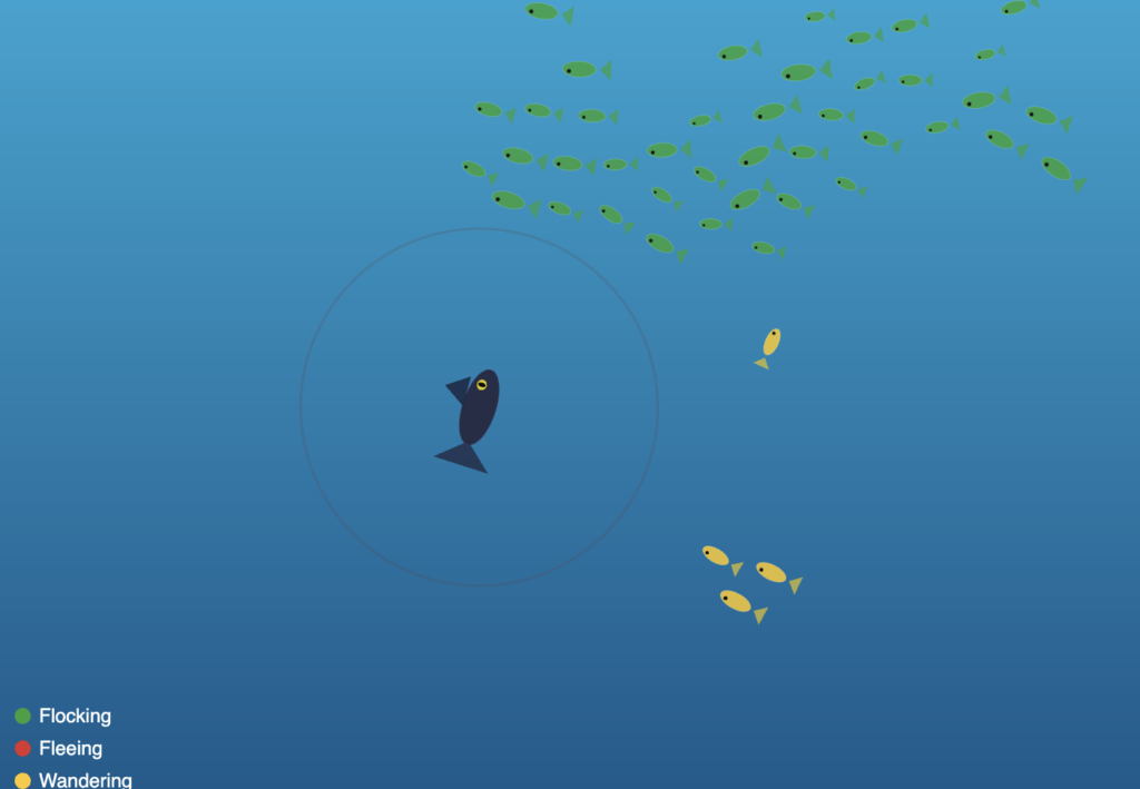
The color palette is drawn from the Ghanaian flag (red, gold, and green), and each color encodes a live behavioral state. Green means a fish is flocking normally. Red means it is fleeing the predator. Gold means it has drifted away from the group and is wandering on its own.
A Highlight of Code I’m Proud Of
The piece of code I kept returning to is the flock() method, the behavior composer that decides frame by frame what each fish should be doing. What I love about it is how it uses the same underlying steering primitives in completely different combinations depending on context.
flock(others, pred, flow) {
  let d = dist(this.pos.x, this.pos.y, pred.pos.x, pred.pos.y);
  let fleeing = d < FLEE_RADIUS;

  if (fleeing) {
    // Run directly away from the predator at boosted speed
    let flee = this._flee(pred.pos);
    flee.mult(2.5);
    this.applyForce(flee);
    this.maxSpeed = FISH_MAX_SPEED * 1.5;
    this.bodyColor = PAL.red;
  } else {
    // Normal flocking: separation keeps spacing, alignment matches heading,
    // cohesion pulls toward the group center using arrive()
    let sep = this._separation(others);
    let ali = this._alignment(others);
    let coh = this._cohesion(others);

    sep.mult(1.8);
    ali.mult(1.0);
    coh.mult(1.2);

    this.applyForce(sep);
    this.applyForce(ali);
    this.applyForce(coh);

    // Flow field gives the fish a subtle current to drift with
    let flowForce = flow.lookup(this.pos);
    flowForce.setMag(this.maxSpeed * 0.6);
    let flowSteer = p5.Vector.sub(flowForce, this.vel);
    flowSteer.limit(this.maxForce * 0.5);
    this.applyForce(flowSteer);

    // Isolated fish switch to wander
    let neighbors = this._countNeighbors(others, COH_RADIUS);
    if (neighbors < 3) {
      this.bodyColor = PAL.gold;
      this.applyForce(this._wander());
    } else {
      this.bodyColor = PAL.green;
    }
  }
}
What made this click for me is that _arrive() is called inside _cohesion(), so even the group behavior uses the same arrive logic I first learned as a single vehicle seeking a target. One method, three behavioral contexts: cohesion toward the group center, the predator arriving at the cursor, and the wander behavior projecting a circle ahead of itself. Reusing the same primitive in different combinations was the most satisfying part of this assignment.
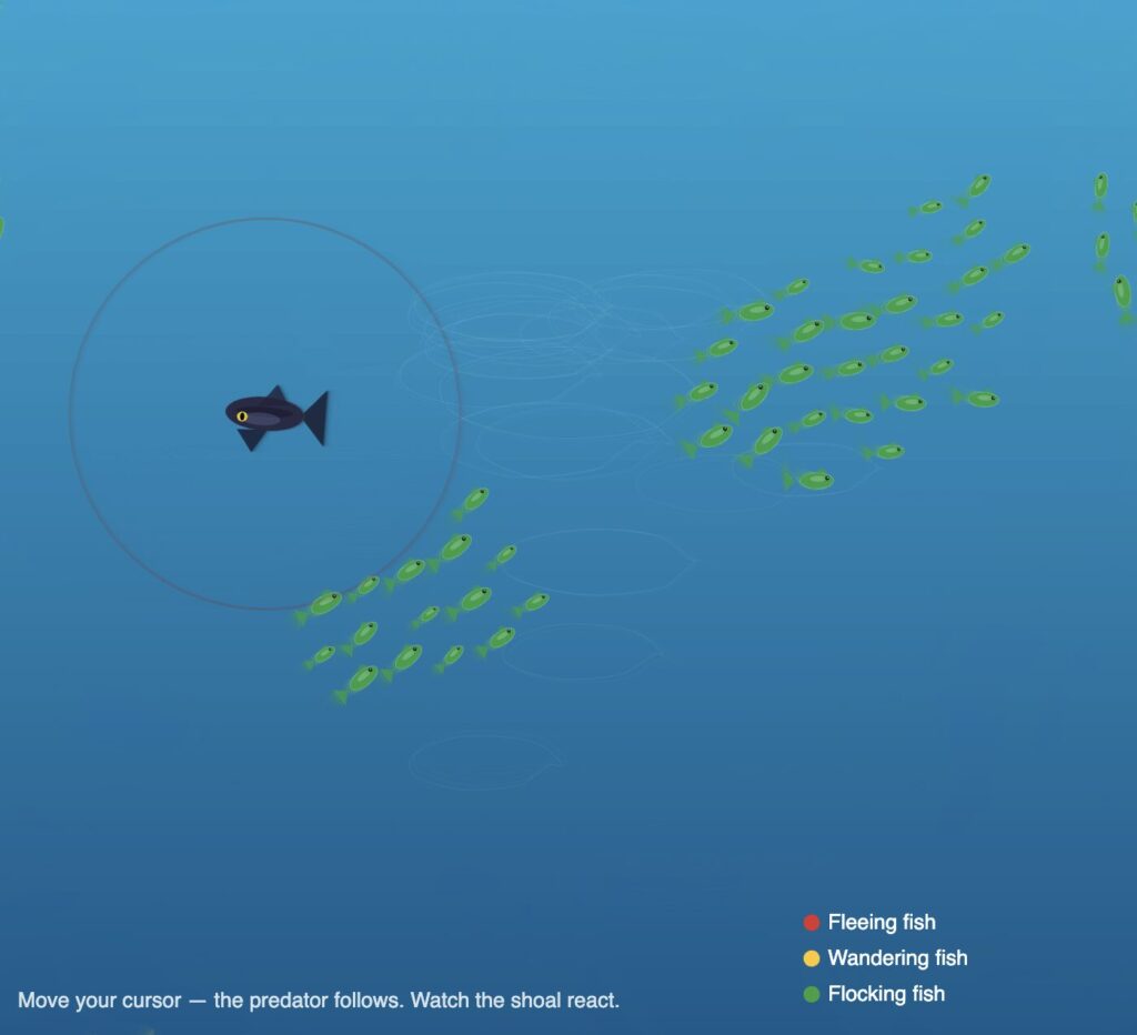
Embedded Sketch
Move your cursor to control the predator. Watch the shoal react. Fish nearest the predator turn red and scatter, isolated fish turn gold and wander, and the rest stay green and hold formation together.
Milestones and Process
Phase 1 — One fish, seek and arrive
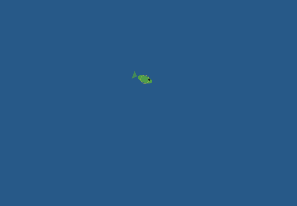
I started with a single fish vehicle following the mouse. The goal was to make sure the arrive behavior felt right before scaling up, because arrive is the foundation everything else builds on. At this stage it was just one ellipse with a triangle tail, but the deceleration as it approached the cursor already felt organic.
The main challenge here was getting the arrive slowing to feel natural rather than mechanical. My first attempt applied the speed reduction too early, so the fish would crawl painfully slowly from far away before even reaching the target zone. I had to narrow the slowdown window to only the final 100 pixels, leaving full speed everywhere outside that range, before the motion started to feel right.
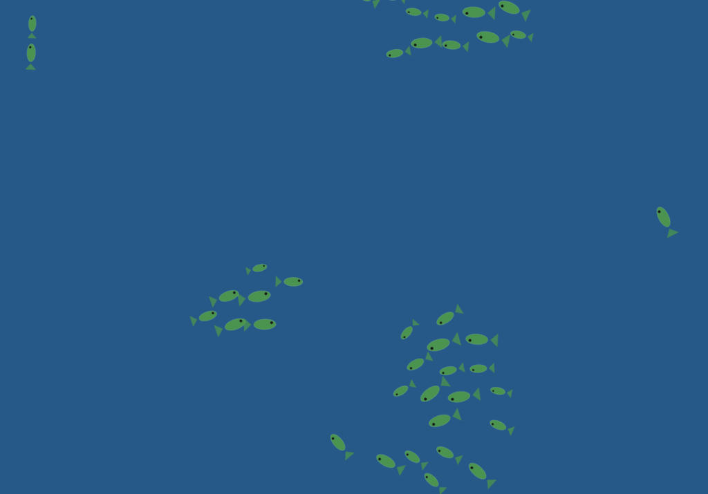
Phase 2 — Scaling to a shoal, adding flocking
I scaled from one fish to 40 using a loop and implemented separation, alignment, and cohesion as three separate steering forces composed together.
Tuning the force multipliers was the hardest part of this phase and took the most iteration. My first set of values had separation too weak, so fish constantly clipped through each other and the group looked like a blob rather than a school. Raising it too far in the other direction made the shoal explode outward and never reform. I also had alignment weighted too heavily early on, which made every fish lock into the same heading so rigidly that the group moved like a marching band rather than a living thing. Getting to sep × 1.8, ali × 1.0, coh × 1.2 took many small adjustments and a lot of watching the sketch run.
Phase 3 — Predator, flee, wander, and color states
The predator changed the whole feel of the sketch. Once a dark fish that tracked the mouse was introduced, the shoal became reactive rather than passive. Flee was implemented as a reversed seek: instead of steering toward the target, the fish steers directly away from it with a force multiplied at 2.5× for urgency.
The flee force caused a problem I did not anticipate. With the multiplier too high, fish near the predator would accelerate so violently that they shot across the entire canvas in a single frame and wrapped around to the other side, which looked completely wrong. I had to pair the force multiplier with a capped maxSpeed boost rather than an uncapped acceleration, so the urgency comes through in the speed increase without the motion becoming physically implausible. Getting the flee radius right also took several attempts. Too large and fish were permanently panicking even when the predator was nowhere near them. Too small and the reaction looked delayed and unconvincing.
Phase 4 — Flow field, ocean background, full fish anatomy
The final layer was a Perlin noise flow field that gives the whole canvas a gentle ocean current. Each fish looks up the flow vector at its position and applies it as a weak additional force.
The challenge here was finding the right weight for the flow force relative to the flocking forces. In early versions I had it too strong, and it completely overrode the cohesion and alignment behavior. Fish stopped schooling and just drifted in the same direction like debris, which defeated the whole point. Pulling it back to maxSpeed × 0.6 with a force limit at half of maxForce made it feel like an environmental influence rather than a controlling force — the fish push through it, but you can see them drifting slightly when nothing else is competing for their attention.
Reflection and Ideas for Future Work
The biggest surprise was how little code produces this result. The entire behavioral system, 60 fish with four distinct modes, comes down to three vector additions per frame per fish, each about five lines long. What Reynolds figured out in the 1980s still feels almost unreasonably powerful.
The Ghanaian flag palette was a natural choice for me. I had already used it in my midterm project, and it works well here because each color carries cultural weight while also reading clearly as a data signal. You understand the system’s state at a glance just from the color distribution across the canvas.
Ideas for future work include adding a real food source, a glowing anchor point the shoal seeks when the predator is far away, which would complete the full foraging cycle. Two competing shoals in different colors racing for the same food would also be compelling. Letting individual fish leave a faint pheromone trail that gradually fades would make the paths the school carves through the water visible over time. And sound would add another dimension: low ambient ocean audio that pitches up slightly when the shoal is stressed and fleeing.
References and inspiration:
The Nature of Code, Chapter 5 (Autonomous Agents) by Daniel Shiffman, which provided the steering force formula the entire system is built on
Craig Reynolds, Steering Behaviors for Autonomous Characters, the original separation, alignment, and cohesion framework
Braitenberg Vehicles, and the idea that complex behavior can emerge from extremely simple rules
Personal memory of fishing communities in the Central Region of Ghana
I wanted to build something that felt genuinely alive, not just shapes moving around a screen, but a system with real logic behind it. I kept coming back to one question: how do ants form those perfect lines without anyone telling them where to go?
The answer is surprisingly simple. One scout finds a path and leaves a chemical trail called a pheromone. Workers smell it and follow. The more ants walk the same path, the stronger the smell, the more ants follow. A highway emerges from nothing, no leader, no plan, just chemistry.
That became the concept. You are the scout. Move your mouse, and the colony follows the exact path you traced. Stop moving, and the scout breaks away to investigate the environment on its own, sniffing nearby rocks while the workers wait in place.
The moment that made everything click was the pebble investigation system. When the mouse stops, the scout doesn’t just freeze, it actively searches for the nearest rock within 120 pixels and slowly approaches it, like an ant sniffing an obstacle. When it gets close enough it clears that target and finds the next one.
// ── LEADER
if (mouseStill) {
  // slow crawl speed while exploring
  leader.maxSpeed = 0.5;
  // clear pebble target once scout is close enough
  if (targetPebble) {
    let d = dist(leader.pos.x, leader.pos.y, targetPebble.x, targetPebble.y);
    if (d < SEEK_STOP) targetPebble = null;
  }
  // find a new pebble if not already investigating one
  if (!targetPebble) targetPebble = findNearestPebble();
  // arrive at pebble slowly, or wander if none nearby
  if (targetPebble) leader.arrive(createVector(targetPebble.x, targetPebble.y));
  else              leader.wander();
What I love about this is that it uses the same arrive() behavior the whole project is built on, just at a slower speed. One behavior, three different contexts: following the mouse, following history points, investigating a rock. That reuse felt elegant.
Embedded Sketch
Milestones and Process
Phase 1 — Getting the chain to work
Started with two plain circles. One follows the mouse using arrive. Every frame, its position gets saved into a history array. The second circle targets history[40], where the first was 40 frames ago. That delay creates the following effect. The main challenge was stopping them from overlapping when the mouse stopped, fixed by only recording history when the leader actually moved.
Phase 2 — Scaling to a colony
Scaled from one follower to seven using a simple loop. Each ant targets a different point further back in history. Added real ant bodies, the sandy background, and separation logic between every pair of ants so they never overlap.
Phase 3 — The Final Sketch
Added the fading pheromone trail, pebble investigation when the mouse stops, workers freezing while the scout explores, and a custom glowing cursor. The final version can be found embedded above.
Reflection and Future Ideas
The biggest surprise was how little code produces this behavior. A five-line loop creates the chain. One Perlin noise value creates the wander. Simple rules, complex result, exactly what the ant research described.
Future ideas:
Add a real food source that the scout can find and bring workers to complete the full foraging loop
Two competing colonies with different trail colors racing to the same food
Make the trail actually fade so workers that fall too far behind lose the scent and wander off alone
When thinking about “autonomous agents” in the nature one thing that came to mind were birds. Most of the time they move around by themselves, deciding on directions and the destination for us seemingly randomly, but when in a flock if they are following a leader suddenly they all come together to move in large groups following one. This is something I wanted to recreate in my project.
The user can click on the screen to spawn the leader bird, which will attract the rest of the flock. After the birds have gathered around it they will start orbiting around instead of all just piling up in one place. After which the user can click on another point on the screen and watch as the birds move towards it, each going their own direction and following the flow and the flock.
Process
I started by just having lines instead of birds as I just wanted to get the autonomous movement going:
After this was done it was time to add the birds. I decided to create them as pretty simple models, but I also wanted to add some flapping of the wings to make the visuals more appealing.
I used the sin function to make the flapping smooth and natural, but I also made sure that the wings don’t move the the same position at the same times, instead when one moves up the other moves down and vice-versa.
Once I was happy with the look I decided to make the leader also a bird and allow the user to click to move it. I also decided to lower the alpha of the background to make the birds leave streaks behind so it gives it more of an art aesthetic.
Code Highlight
separate(vehicles) {
  let perceptionRadius = 25;
  let steering = createVector();
  let total = 0;

  for (let other of vehicles) {
    let d = dist(this.pos.x, this.pos.y, other.pos.x, other.pos.y);

    if (other !== this && d < perceptionRadius && d > 0) {
      let diff = p5.Vector.sub(this.pos, other.pos);
      diff.div(d * d);
      steering.add(diff);
      total++;
    }
  }

  if (total > 0) {
    steering.div(total);
    steering.setMag(this.maxSpeed);
    steering.sub(this.vel);
    steering.limit(this.maxForce * 1.2);
    this.applyForce(steering);
  }
}
One important action in this system is separation, where no two birds overlap and flock structure is maintained. Each bird looks at its local neighbors and applies a repulsive force that increases with proximity. The repulsive force increases significantly as distance decreases because it is divided by the square of the distance. This produces a natural spacing effect so that the flock is cohesive but not overly dense.
I would also like to highlight this part of the code:
Instead of clearing the screen and redrawing the background each frame I decided to dram a rectangle over the screen with a certain color and decrease its alpha. This gradually fades the previous frames instead of just clearing them instantly which makes the birds’ previous position to be visible for a short duration of time. This motion blur is something I wanted to create so we can better visualize the movement of the birds and it also allows the user to create a canvas where they paint on by moving the leader and letting the birds paint as they move towards it.
Future improvements
I am really proud of how the project turned out in the end. If I was to add any other features that would probably be adding different colors for the birds and their trails as well as maybe playing with sound somehow as that is something I haven’t really worked on much before. Overall I am happy with the end result and have learned more about p5 while working on it.
My concept is inspired by fireworks. I wanted to explore how this week’s vehicle demonstrations could be transformed into something more artistic, which I initially found challenging. When I first think of vehicles, I usually imagine something literal like cars, so it took some time to shift my thinking toward a more abstract approach. I used the flow field example from class as a starting point and built on it to create a system that feels more expressive.
A highlight of some code
behaviors(flow) {
// explode outward first
this.seek(this.target);

// soften near destination
this.arrive(this.target);

// drift like smoke/wind after burst
if (this.life < 55) {
this.follow(flow);
}
}

seek(t) {
let desired = p5.Vector.sub(t, this.pos);
desired.setMag(this.maxSpeed);

let steering = p5.Vector.sub(desired, this.vel);
steering.limit(this.maxForce);

this.applyForce(steering);
}

arrive(t) {
let desired = p5.Vector.sub(t, this.pos);
let d = desired.mag();

if (d < 60) {
let m = map(d, 0, 60, 0, this.maxSpeed);
desired.setMag(m);
} else {
desired.setMag(this.maxSpeed);
}

let steering = p5.Vector.sub(desired, this.vel);
steering.limit(this.maxForce * 0.8);

this.applyForce(steering);
}

follow(flow) {
let desired = flow.lookup(this.pos);
desired.setMag(this.maxSpeed * 0.7);

let steering = p5.Vector.sub(desired, this.vel);
steering.limit(this.maxForce * 0.6);

this.applyForce(steering);
}
This is the part I’m most proud of because it is where the vehicles stop being just particles and start behaving like fireworks. Instead of using only one steering behavior, I combined three different ones so each particle goes through stages of motion.
First, seek() pushes each vehicle outward toward its explosion target, which creates the initial burst. Then arrive() slows the particle as it gets closer to that target, so the explosion doesn’t feel too mechanical or constant. After that, once the particle’s life drops below a certain point, follow() lets it drift with the flow field, which makes it look more like smoke or sparks being carried by air.
Sketch
Milestones
I combined the flow field with a basic explosion system. Vehicles are created at a point and use seek to move outward, while still being influenced by the flow field. The visualization is simple to focus on the behavior before adding artistic styling.https://youtu.be/0gokb2LBqo0
I added arrival behavior, particle lifespan, and fading trails so the explosion becomes more natural and starts to resemble fireworks instead of just moving points.
Reflection and ideas for future work or improvements
This assignment made me think about vehicles in a different way, because when I first hear “vehicle,” I usually imagine something literal like cars and that’s why it was hard at first to think of a concept. I used vehicles as abstract moving particles to create a firework system, which helped me see them more as agents following rules rather than physical objects. I was able to build motion that feels more expressive and dynamic. In the future, I would like to push this idea further by adding more variation in the explosions and refining the overall visual style.
For my project I wanted to replicate the movement of birds between trees and their pathing around obstacles, in this case mountains. To best visualize this I started with a top-down view and then to make the sketch more visually pleasing I used contour lines to replicate a topographic map.
I was first inspired to do a simulation with birds by the garden outside my house in Dubai. Put simply there are a lot of birds, many are pigeons or sometimes crows as far as I can tell. From what I’ve seen most birds travel in packs and follow a similar direction to each other and at our house they often travel from tree to tree within the garden or with the trees lining the walls of my neighbours then they may stay at a tree for a while before moving again but always following a similar path in the air. Similarly, I see some birds stop at our pool to drink water often altogether. I wanted to replicate this behaviour in my project.
In addition, after deciding to do the simulation from a top down view I decided to add contour lines and make it appear to be a topographic map because it’s an idea I have been exploring for a while. I first learned how to make basic contour lines in photoshop using noise and since wanted to find places to use it since I feel it doesn’t get as much use as it should.
Implementation Details
This simulation is built around trees as emitters, birds as moving agents, a flow field for natural motion, mountains as obstacles that affect the vector field, contour lines for terrain, and a UI panel that lets you change parameters in real time.
Bird class
The Bird class represents one moving agent that travels between trees. Each bird stores position, destination, destination tree index, arrival/wait state, size, trail history, and a day-only behavior flag.
A destination tree is chosen randomly.
The bird travels to its destination.
When they arrive, they wait for a random duration.
After waiting, they pick a new destination tree at random.
Their movement is not only direct-to-target; a vector field is used for more natural movement.
The Tree class is both a visual node and an emitter for birds. Each tree has x and y coordinates, a diameter, and its own bird array.
A tree can initialize a number of birds.
Each spawned bird gets this tree as origin and a different tree as destination.
The tree updates and draws all birds in its own array.
class Tree {

  constructor(x, y, diameter = 40) {

    this.x = x;

    this.y = y;

    this.diameter = diameter;

    this.birdArray = [];

  }

}
The pathing starts with a direct vector from bird position to destination. Then the code samples the flow field at the bird position and then using vector addition it changes the heading of the bird itself.
let toDest = p5.Vector.sub(this.des, this.pos);

let desired = toDest.copy().setMag(birdSpeed);
let flow = getFlowAt(this.pos.x, this.pos.y);

let steer = desired.add(flow.mult(0.6));

steer.limit(birdSpeed + 0.5);

this.pos.add(steer);
function updateFlowField() {

  let noiseScale = 0.02;

  let time = frameCount * 0.005;

  for (let y = 0; y < flowFieldRows; y++) {

    for (let x = 0; x < flowFieldCols; x++) {

      let angle = noise(x * noiseScale, y * noiseScale, time) * TWO_PI * 2;

      flowField[y][x] = p5.Vector.fromAngle(angle).mult(0.8);

    }

  }

}
Mountain generation
Mountains are generated by sampling terrain elevation candidates from noise (to make spawning more natural as opposed to complete randomness), sorting candidates by highest elevation first, then placing mountains with spacing constraints.
const candidates = buildMountainCandidates();

for (let i = 0; i < candidates.length && mountains.length < quantity; i++) {

  const c = candidates[i];

  const baseRadius = map(c.elevation, 0, 1, mountainMinRadius, mountainMaxRadius, true);

  const radius = baseRadius * random(0.9, 1.12);

  const x = c.x;

  const y = c.y;

  if (isMountainPlacementValid(x, y, radius, 1, true)) {

    mountains.push({ x, y, radius });

  }

}
Mountains do not rewrite the global flow field grid directly. Instead, there’s an additional tangential force that gets added to the bird’s steer direction, not the vector field.
Last but not least there are multiple states in the program. Day and Night, and with or without mountains. I decided to keep the states simple for this project. Day and night have visual changes and mountains affect the movements of the birds.
Milestones
Version 1
This was one of my first versions of my sketch it consisted of trees that were randomly spawned around the canvas (later I would switch to using random) and birds that travelled inbetween and there is the vector field although it is hard to notice in this image. There are some small details I implemented as well like birds would stop at the edge of the tree and I made the opacity of the background low so that I could see the paths of the birds more clearly.
Version 2
At this point I created the Mountain class, it would be different sizes and I just had it spawn randomly around the canvas at this point and I could change how many would spawn. As you can see at this point I didn’t implement the avoidance as you can see by the trail of one bird at the bottom that phased through the mountain.
Version 3
From my perspective at this point I had overcome the most important technical features. I now had birds that travelled between trees that moved organically and could avoid mountains and I was happy with the effect but I knew there was potential to make it more aesthetically pleasing but I didn’t know what my next step would be.
Version 4 (Daytime and Nighttime)
At this point I had simply implemented two states of it either being day or being night. Later I added a version of birds which would only move during the day and would stay at their trees during the night and a transition effect from day to night.
Version 5 (User Interface)
I took all the features I had before and now I added a user interface in the form of sliders at the bottom of the canvas. Because it changed the canvas in real time it allowed me to see different variations and it led to the idea of making the mountains spawn using noise but only at points of ‘highest elevation’. This later led to the idea of the topographic map.
Version 6
I started with just topographic lines with the noise function alone (not taking into consideration the placement of mountains) then after tweaking the strokeWeight to make it more visible I added the mountains in the form of the contour lines. Then I added colors based on the elevation opting for a sand color and for the areas of low elevation a blue color to represent water and for the mountains a gray color but I later tweaked the gray color and sand color to make it more prominent.
Version 7
This is the latest version of my sketch. From the last version to this I added a few more elements that can be changed from the UI (not shown in this screenshot) and
(Looks better when viewing it on a larger canvas)
Video Documentation
Reflection
I’m happy with the movement of the birds especially the avoidance of the mountains. However, I wasn’t able to get an A3 sized screenshot of the simulation because it is too slow when scaled to be A3 sized. I’m not sure why exactly I haven’t taken the time to sit down and figure it out but I have a suspicion that its because of the size of the vector field and all the vector calculations. I’m just guessing.
I would also want to make improvements on the aesthetics. I thought about shadows and maybe having more detailed models for the birds and trees but I wasn’t sure how to without going against the topographic map aesthetic.
References
p5.js library — p5js.org
Daniel Shiffman, The Nature of Code: vector movement and flow fields (natureofcode.com)
AI disclosure: To assist with the mountain repulsion force implementation and the contour line generation using the Marching Squares algorithm
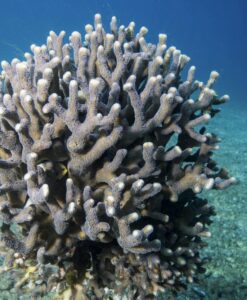
This sketch visualizes thoughts as a living system, behaving somewhere between a school of fish and coral formations. I was especially drawn to corals as a reference, not just visually but structurally. Corals are collective, slow, reactive organisms that grow through accumulation and interaction rather than control. That felt very aligned with how thoughts operate.
Instead of treating thoughts as isolated units, I approached them as a soft ecosystem. They cluster, avoid, drift, and react to an external stimulus, which in this case is the mouse acting as a “focus point” or “idea.” When the interaction is calm, thoughts gather and stabilize. When it becomes too fast or erratic, they scatter, almost like a disturbance in water.
There’s also influence from generative systems like flocking and steering behaviors, but I wanted to move away from purely mechanical logic and make it feel more emotional. The system shifts between states: wandering, focusing, and panicking. That transition is what makes it feel alive to me.
Code Highlight (something I’m proud of)
One part I’m particularly proud of is the behavior system tied to mouse speed, especially how it shifts between different “mental states”:
I like this because it’s simple but expressive. It turns a technical input (mouse velocity) into something that feels psychological. The system isn’t just moving, it’s reacting, almost like attention and overwhelm are being simulated.
Embedded Sketch
Milestones
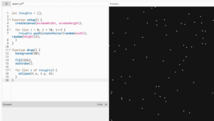
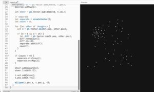
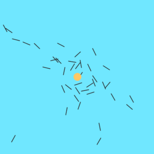
✦ milestone 1 baseline dots
it started as just points on a screen, nothing intelligent, nothing reactive. just scattered presence. like the baseline state of a mind before anything kicks in, just existing, quiet but full.
✦ milestone 2 random motion
then they started moving, but without direction. drifting, floating, no purpose. it felt like background thoughts, the kind that just pass through you when you’re not paying attention to anything specific.
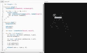
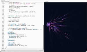
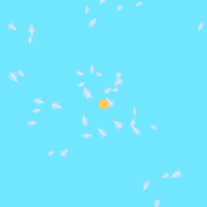
✦ milestone 3 steering toward focus
this is where intention entered. everything began to move toward the mouse, like trying to focus on something. it’s not perfect, it overshoots, it adjusts, but there’s a clear pull. like when you’re trying to gather your thoughts into one place.
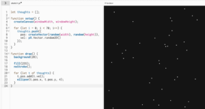
✦ milestone 4 separation
once everything started gathering, it became too much, everything overlapping, collapsing into one point. so separation was introduced. thoughts began to keep distance from each other, like needing space to think clearly. it stopped being chaos and started feeling structured.
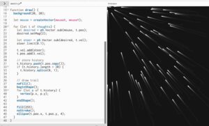
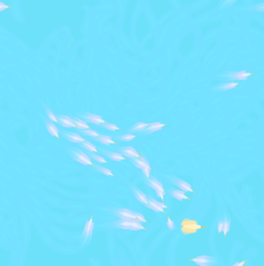
✦ milestone 5 trails (memory)
then memory appeared. each thought started leaving a trace behind it. nothing fully disappears anymore. even when it moves on, something lingers. this is where the system stopped feeling like motion and started feeling like time.
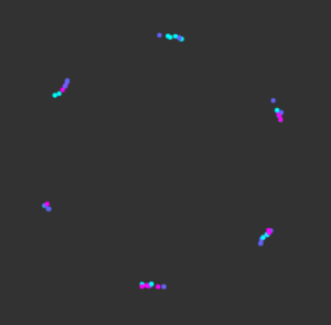
✦ milestone 6 color and mood
movement started affecting visuals. faster thoughts became brighter, more intense. slower ones stayed softer. the system began expressing mood, not just behavior. it became less about where things are and more about how they feel.
Reflection + Future Work
This project made me think a lot about how behavior systems can move beyond being purely functional and start becoming expressive. Small parameter changes completely shift the emotional tone of the piece, which I found really interesting.
If I were to develop this further, I would push it in a few directions. I want to explore more coral-like growth over time, where thoughts don’t just move but also accumulate or leave behind structure. Right now, everything is transient, but memory could become spatial.
I’m also interested in introducing clusters or hierarchies, where some thoughts carry more weight or influence others, instead of everything behaving equally. That could create moments of tension or dominance within the system.
Visually, I would refine the trails to feel even more organic, maybe closer to underwater motion or bioluminescence. Sound could also be interesting, where movement generates subtle audio feedback tied to speed or density.
This feels like a starting point for thinking about systems as emotional landscapes, not just simulations.


 At this point I created the Mountain class, it would be different sizes and I just had it spawn randomly around the canvas at this point and I could change how many would spawn. As you can see at this point I didn’t implement the avoidance as you can see by the trail of one bird at the bottom that phased through the mountain.